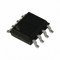
FAN4803CS2 Fairchild Semiconductor, FAN4803CS2 Datasheet - Page 7

FAN4803CS2
Manufacturer Part Number
FAN4803CS2
Description
IC CTRLR PFC/PWM 67/134KHZ 8SOIC
Manufacturer
Fairchild Semiconductor
Datasheet
1.FAN4803CP2.pdf
(12 pages)
Specifications of FAN4803CS2
Mode
Average Current
Frequency - Switching
67kHz
Current - Startup
200µA
Voltage - Supply
10 V ~ 15 V
Operating Temperature
0°C ~ 70°C
Mounting Type
Surface Mount
Package / Case
8-SOIC (3.9mm Width)
Switching Frequency
134 KHz
Maximum Operating Temperature
+ 70 C
Mounting Style
SMD/SMT
Minimum Operating Temperature
0 C
Lead Free Status / RoHS Status
Lead free / RoHS Compliant
Other names
FAN4803CS2_NL
FAN4803CS2_NL
FAN4803CS2_NL
Available stocks
Company
Part Number
Manufacturer
Quantity
Price
Part Number:
FAN4803CS2
Manufacturer:
F
Quantity:
20 000
Company:
Part Number:
FAN4803CS2X
Manufacturer:
FSC
Quantity:
1 000
PRODUCT SPECIFICATION
REV. 1.2.3 11/2/04
R
R
C
C
V EAO +
COMP
COMP
FAN4803
ZERO
ZERO
–
=
=
=
=
100
150
200
50
2
6 28
62 8 30
2
0
.
0.1
.
Figure 6. Voltage Loop Phase
Figure 4. Voltage Control Loop
POWER
STAGE
I OUT
3
10
f C
Hz
f
1
1
1
1
Hz
1
220 F
COMP
R
330
COMP
FREQUENCY (Hz)
16
COMPENSATION
nF
k
V O
R LOAD
667
0.15 F
=
=
10
330
016
.
k
11.3M
330k
F
Power Stage
Overall
Compensation
15nF
Network
100
VEAO
1000
FAN4803
I VEAO
34 A
(3)
(4)
Internal Voltage Ramp
The internal ramp current source is programmed by way of
the VEAO pin voltage. Figure 7 displays the internal ramp
current vs. the VEAO voltage. This current source is used to
develop the internal ramp by charging the internal 30pF +12/
–10% capacitor. See Figures 10 and 11. The frequency of the
internal programming ramp is set internally to 67kHz.
PFC Current Sense Filtering
In DCM, the input current wave shaping technique used by
the FAN4803 could cause the input current to run away.
In order for this technique to be able to operate properly
under DCM, the programming ramp must meet the boost
inductor current down-slope at zero amps. Assuming the
programming ramp is zero under light load, the OFF-time
will be terminated once the inductor current reaches zero.
Figure 7. Internal Ramp Current vs. VEAO
50
40
30
20
10
–20
–40
–60
0
60
40
20
0
0
0.1
FF @ –55ºC
TYP @ –55ºC
TYP @ ROOM TEMP
TYP @ 155ºC
SS @ 155ºC
Figure 5. Voltage Loop Gain
1
2
1
FREQUENCY (Hz)
V EAO (V)
3
10
4
5
Power Stage
Overall Gain
Compensation
Network Gain
100
6
FAN4803
7
1000
7


