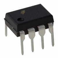
KA3843B Fairchild Semiconductor, KA3843B Datasheet - Page 7

KA3843B
Manufacturer Part Number
KA3843B
Description
IC CONTROLLER PWM SMPS 8-DIP
Manufacturer
Fairchild Semiconductor
Datasheet
1.KA3843B.pdf
(10 pages)
Specifications of KA3843B
Pwm Type
Current Mode
Number Of Outputs
1
Frequency - Max
500kHz
Duty Cycle
100%
Voltage - Supply
8.2 V ~ 30 V
Buck
No
Boost
No
Flyback
No
Inverting
No
Doubler
No
Divider
No
Cuk
No
Isolated
No
Operating Temperature
0°C ~ 70°C
Package / Case
8-DIP (0.300", 7.62mm)
Frequency-max
500kHz
Duty Cycle (max)
100 %
Output Current
1000 mA
Mounting Style
Through Hole
Switching Frequency
500 KHz
Supply Current
17 mA
Maximum Operating Temperature
+ 70 C
Fall Time
35 ns
Minimum Operating Temperature
0 C
Rise Time
45 ns
Synchronous Pin
No
Input Voltage
15V
Output Voltage
5V
Frequency
500kHz
Power Dissipation Pd
1.2W
Supply Voltage Range
12V To 25V
Digital Ic Case Style
DIP
No. Of Pins
8
Rohs Compliant
Yes
Number Of Pwm Outputs
1
On/off Pin
No
Adjustable Output
No
Switching Freq
500kHz
Operating Supply Voltage (max)
30V
Operating Temperature Classification
Commercial
Mounting
Through Hole
Pin Count
8
Package Type
PDIP
Lead Free Status / RoHS Status
Lead free / RoHS Compliant
Available stocks
Company
Part Number
Manufacturer
Quantity
Price
Company:
Part Number:
KA3843B
Manufacturer:
FAIRCHILD
Quantity:
1 594
Company:
Part Number:
KA3843B
Manufacturer:
Fairchi/ON
Quantity:
1 600
Shutdown of the KA3842B can be accomplished by two methods; either raise pin 3 above 1V or pull pin 1 below a voltage
two diode drops above ground. Either method causes the output of the PWM comparator to be high (refer to block diagram).
The PWM latch is reset dominant so that the output will remain low until the next clock cycle after the shutdown condition at
pins 1 and/or 3 is removed. In one example, an externally latched shutdown may be accomplished by adding an SOR which
will be reset by cycling V
A fraction of the oscillator ramp can be resistively summed with the current sense signal to provide slope compensation for
converters requiring duty cycles over 50%. Note that capacitor, C
spikes.
Figure 10. Temperature Drift (Vref)
Figure 12. Temperature Drift (Icc)
TEMPERATURE ( C)
TEMPERATURE ( C)
CC
below the lower UVLO threshold. At this point the reference turns off, allowing the SCR to reset.
Figure 9. Slope Compensation
T
, forms a filter with R2 to suppress the leading edge switch
Figure 11. Temperature Drift (Ist)
TEMPERATURE ( C)
KA3842B/KA3843B/KA3844B/KA3845B
7


