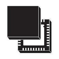
L6722TR STMicroelectronics, L6722TR Datasheet - Page 8

L6722TR
Manufacturer Part Number
L6722TR
Description
IC BUCK ADJ 2A TRPL 36VFQFPN
Manufacturer
STMicroelectronics
Type
Step-Down (Buck)r
Datasheet
1.L6722TR.pdf
(34 pages)
Specifications of L6722TR
Internal Switch(s)
No
Synchronous Rectifier
No
Number Of Outputs
3
Voltage - Output
Adj to 0.8V
Current - Output
2A
Frequency - Switching
100kHz
Voltage - Input
12V
Operating Temperature
0°C ~ 70°C
Mounting Type
Surface Mount
Package / Case
36-VFQFN, 36-VFQFPN
Power - Output
3.5W
Operating Temperature Range
- 40 C to + 125 C
Mounting Style
SMD/SMT
Lead Free Status / RoHS Status
Lead free / RoHS Compliant
Other names
497-5904-2
Available stocks
Company
Part Number
Manufacturer
Quantity
Price
2 Pins description and connection diagrams
8/34
Table 1.
Pin#
10
11
12
13
14
15
16
17
18
19
20
21
22
9
Pins description (continued)
UGATE1
PHASE1
UGATE2
PHASE2
UGATE3
PHASE3
LGATE2
LGATE3
PGOOD
BOOT1
BOOT2
BOOT3
Name
N.C.
N.C.
Channel 2 LS Driver Output.
A small series resistor helps in reducing device-dissipated power.
Channel 3 LS Driver Output.
A small series resistor helps in reducing device-dissipated power.
Channel 1 HS driver supply.
Connect through a capacitor (100nF typ.) to PHASE1 and provide
necessary Bootstrap diode.
A small series resistor before the boot diode helps in reducing Boot
capacitor overcharge.
Channel 1 HS driver output.
A small series resistors helps in reducing device-dissipated power.
Channel 1 HS driver return path.
It must be connected to the HS1 mosfet source and provides return path
for the HS driver of channel 1.
Channel 2 HS driver supply.
Connect through a capacitor (100nF typ.) to PHASE2 and provide
necessary Bootstrap diode.
A small series resistor before the boot diode helps in reducing Boot
capacitor overcharge.
Channel 2 HS driver output.
A small series resistors helps in reducing device-dissipated power.
Channel 2 HS driver return path.
It must be connected to the HS2 mosfet source and provides return path
for the HS driver of channel 2.
Channel 3 HS driver supply.
Connect through a capacitor (100nF typ.) to PHASE3 and provide
necessary Bootstrap diode.
A small series resistor before the boot diode helps in reducing Boot
capacitor overcharge.
Channel 3 HS driver output.
A small series resistors helps in reducing device-dissipated power.
Channel 3 HS driver return path.
It must be connected to the HS3 mosfet source and provides return path
for the HS driver of channel 3.
Not Internally Bonded.
Open Drain Output set free after SS has finished and pulled low when
VSEN is lower than the relative threshold. Pull up to a voltage lower than
5V (typ), if not used it can be left floating.
Not Internally Bonded.
Function
L6722


