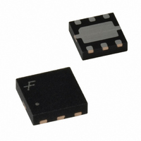
FAN2013MPX Fairchild Semiconductor, FAN2013MPX Datasheet

FAN2013MPX
Specifications of FAN2013MPX
Available stocks
Related parts for FAN2013MPX
FAN2013MPX Summary of contents
Page 1
... Notebook Computer Communications Equipment Typical Application 10K 10µF Ordering Information Part Number Output Voltage FAN2013MPX 0. All packages are lead free per JEDEC: J-STD-020B standard. © 2006 Fairchild Semiconductor Corporation FAN2013 Rev. 1.0.3 Description The synchronous Pulse Width Modulated (PWM) current mode DC-DC converter designed for low-voltage applications ...
Page 2
... AGND Switching Node. This pin is connected to the internal MOSFET switches. 4 PVIN Supply Voltage Input. This pin is connected to the internal MOSFET switches. 5 VIN Supply Voltage Input Open Drain Power Good. © 2006 Fairchild Semiconductor Corporation FAN2013 Rev. 1.0 PGND 2 5 (AGND Figure 2 ...
Page 3
... C Input Capacitor IN (3) C Output Capacitor OUT T Operating Ambient Temperature Range A Note: 3. Refer to the Applications section for details. © 2006 Fairchild Semiconductor Corporation FAN2013 Rev. 1.0.3 Parameter (1) ( strong function of PCB material, board thickness, thickness and JA Parameter 3 Min. Max. -0.3 6.2 -0.3 ...
Page 4
... Power Good Voltage Low PG_LOW Over-Voltage Protection V OVP Threshold and Hysteresis Notes: 4. Please refer to the load transient response test waveform shown in Figure 3. 1500 100ns 100 0 © 2006 Fairchild Semiconductor Corporation FAN2013 Rev. 1.0.3 = 200mA 10µF, C OUT IN OUT = 25°C. A Conditions I = 0mA OUT ...
Page 5
... A IN OUT Figure 4. Start-up with 100mA Resistive Load Figure 6. Load Transient Response 1.5A to 100mA Figure 8. Output Voltage Regulation © 2006 Fairchild Semiconductor Corporation FAN2013 Rev. 1.0 1.2V, unless otherwise noted. IN OUT Figure 5. Start-up with 2A Resistive Load Figure 7. Load Transient Response 100mA to Figure 9 ...
Page 6
... P-channel switch on resistance DS_ON I = Output current LOAD R = Inductor DC resistance L UVLO and Soft Start The internal voltage reference, V reset until V reaches the 3.7V UVLO threshold. IN © 2006 Fairchild Semiconductor Corporation FAN2013 Rev. 1.0.3 PG REF PG COMP FB UNDER VOLTAGE LOCKOUT GND DIGITAL SOFT START ERROR ...
Page 7
... Vendor Value Taiyo Yuden 10µF TDK Murata © 2006 Fairchild Semiconductor Corporation FAN2013 Rev. 1.0.3 PCB Layout Recommendations The inherently high peak currents and switching frequency of power supplies require a careful PCB layout design. For best results, use wide traces for high- ...
Page 8
... Package drawings are provided as a service to customers considering Fairchild components. Drawings may change in any manner without notice. Please note the revision and/or date on the drawing and contact a Fairchild Semiconductor representative to verify or obtain the most recent revision. Package specifications do not expand the terms of Fairchild’s worldwide terms and conditions, specifically the warranty therein, which covers Fairchild products. Always visit Fairchild Semiconductor’ ...
Page 9
... Fairchild Semiconductor Corporation FAN2013 Rev. 1.0.3 9 www.fairchildsemi.com ...


