MT18VDDF12872HY-335D1 Micron Technology Inc, MT18VDDF12872HY-335D1 Datasheet - Page 19
MT18VDDF12872HY-335D1
Manufacturer Part Number
MT18VDDF12872HY-335D1
Description
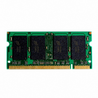
MODULE SDRAM DDR 512MB 200SODIMM
Manufacturer
Micron Technology Inc
Datasheet
1.MT18VDDF12872HY-335D1.pdf
(27 pages)
Specifications of MT18VDDF12872HY-335D1
Memory Type
DDR SDRAM
Memory Size
1GB
Speed
333MT/s
Package / Case
200-SODIMM
Main Category
DRAM Module
Sub-category
DDR SDRAM
Module Type
200SODIMM
Device Core Size
72b
Organization
128Mx72
Total Density
1GByte
Chip Density
512Mb
Access Time (max)
700ps
Maximum Clock Rate
333MHz
Operating Supply Voltage (typ)
2.5V
Operating Current
1.53A
Number Of Elements
18
Operating Supply Voltage (max)
2.7V
Operating Supply Voltage (min)
2.3V
Operating Temp Range
0C to 65C
Operating Temperature Classification
Commercial
Pin Count
200
Mounting
Socket
Lead Free Status / RoHS Status
Lead free / RoHS Compliant


09005aef80e487d7
DDF18C64_128x72HG_A.fm - Rev. A 10/03 EN
30.
31. READs and WRITEs with auto precharge are not
32. Any positive glitch must be less than 1/3 of the
33. Normal Output Drive Curves:
Figure 8: Pull-Down Characteristics
t
minimum actually applied to the device CK and
CK# inputs, collectively during bank active.
allowed to be issued until
fied prior to the internal precharge command
being issued.
clock and not more than +400mV or 2.9V, which-
ever is less. Any negative glitch must be less than
1/3 of the clock cycle and not exceed either -
300mV or 2.2V, whichever is more positive.
HP min is the lesser of
a. The full variation in driver pull-down current
b. The variation in driver pull-down current
c. The full variation in driver pull-up current
d. The variation in driver pull-up current within
e. The full variation in the ratio of the maximum
from minimum to maximum process, temper-
ature and voltage will lie within the outer
bounding lines of the V-I curve of Figure 8,
Pull-Down Characteristics.
within nominal limits of voltage and tempera-
ture is expected, but not guaranteed, to lie
within the inner bounding lines of the V-I
curve of Figure 8, Pull-Down Characteristics.
from minimum to maximum process, temper-
ature and voltage will lie within the outer
bounding lines of the V-I curve of Figure 9,
Pull-Up Characteristics.
nominal limits of voltage and temperature is
expected, but not guaranteed, to lie within the
inner bounding lines of the V-I curve of Figure
9, Pull-Up Characteristics.
to minimum pull-up and pull-down current
should be between 0.71 and 1.4, for device
t
t
CL minimum and
RAS(MIN) can be satis-
t
CH
19
34. The voltage levels used are derived from a mini-
35. V
36. V
37. This maximum value is derived from the refer-
38. For slew rates greater than 1V/ns the (LZ) transi-
39. During Initialization, V
40. The current Micron part operates below the slow-
mum V
practice, the voltage levels obtained from a prop-
erly terminated bus will provide significantly dif-
ferent voltage values.
pulse width £ 3ns and the pulse width can not be
greater than 1/3 of the cycle rate. V
V
pulse width can not be greater than 1/3 of the
cycle rate.
enced test load. In practice, the values obtained
in a typical terminated design may reflect up to
310ps less for
(MAX) will prevail over
(MAX) condition.
t
tion will start about 310ps earlier.
be equal to or less than V
V
even if V
of 42 W of series resistance is used between the V
supply and the input pin.
est JEDEC operating frequency of 83 MHz. As
such, future die may not reflect this option.
Figure 9: Pull-Up Characteristics
f. The full variation in the ratio of the nominal
DQSCK (MIN) +
Micron Technology, Inc., reserves the right to change products or specifications without notice.
IH
IL
DD
TT
drain-to-source voltages from 0.1V to 1.0V, and
at the same voltage and temperature.
pull-up to pull-down current should be unity
±10 percent, for device drain-to-source volt-
ages from 0.1V to 1.0V.
(MIN) = -1.5V for a pulse width £ 3ns and the
512MB, 1GB (x72, ECC, DR)
and V
may be 1.35V maximum during power up,
overshoot: V
DD
DD
DD
level and the referenced test load. In
/V
200-PIN DDR SODIMM
Q must track each other.
DD
t
HZ(MAX) and the last DVW.
Q are 0.0V, provided a minimum
t
RPRE (MAX) condition.
IH
t
LZ (MIN) will prevail over
(MAX) = V
DD
t
DQSCK (MAX) +
DD
Q, V
+ 0.3V. Alternatively,
TT
DD
, and V
©2003 Micron Technology, Inc.
Q + 1.5V for a
IL
undershoot:
REF
t
RPST
must
t
HZ
TT
Related parts for MT18VDDF12872HY-335D1
Image
Part Number
Description
Manufacturer
Datasheet
Request
R

Part Number:
Description:
IC SDRAM 64MBIT 133MHZ 54TSOP
Manufacturer:
Micron Technology Inc
Datasheet:

Part Number:
Description:
IC SDRAM 64MBIT 5.5NS 86TSOP
Manufacturer:
Micron Technology Inc
Datasheet:
Part Number:
Description:
IC SDRAM 64MBIT 200MHZ 86TSOP
Manufacturer:
Micron Technology Inc
Datasheet:
Part Number:
Description:
IC SDRAM 64MBIT 133MHZ 54TSOP
Manufacturer:
Micron Technology Inc
Datasheet:
Part Number:
Description:
IC SDRAM 128MBIT 133MHZ 54TSOP
Manufacturer:
Micron Technology Inc
Datasheet:

Part Number:
Description:
IC SDRAM 256MBIT 133MHZ 90VFBGA
Manufacturer:
Micron Technology Inc
Datasheet:
Part Number:
Description:
IC SDRAM 128MBIT 133MHZ 54TSOP
Manufacturer:
Micron Technology Inc
Datasheet:
Part Number:
Description:
IC SDRAM 256MBIT 133MHZ 54TSOP
Manufacturer:
Micron Technology Inc
Datasheet:

Part Number:
Description:
IC DDR SDRAM 512MBIT 6NS 66TSOP
Manufacturer:
Micron Technology Inc
Datasheet:
Part Number:
Description:
IC SDRAM 128MBIT 167MHZ 86TSOP
Manufacturer:
Micron Technology Inc
Datasheet:
Part Number:
Description:
IC SDRAM 128MBIT 143MHZ 86TSOP
Manufacturer:
Micron Technology Inc
Datasheet:

Part Number:
Description:
SDRAM 256M-BIT 1.8V 54-PIN VFBGA
Manufacturer:
Micron Technology Inc
Datasheet:
Part Number:
Description:
IC SDRAM 128MBIT 143MHZ 86TSOP
Manufacturer:
Micron Technology Inc
Datasheet:

Part Number:
Description:
IC SDRAM 128MBIT 125MHZ 54VFBGA
Manufacturer:
Micron Technology Inc
Datasheet:
Part Number:
Description:
IC SDRAM 128MBIT 125MHZ 54VFBGA
Manufacturer:
Micron Technology Inc
Datasheet: