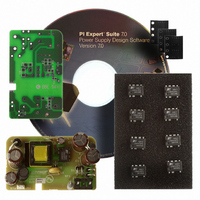
RDK-201 Power Integrations, RDK-201 Datasheet - Page 6

RDK-201
Manufacturer Part Number
RDK-201
Description
KIT REF DESIGN LINKSWITCH-CV
Manufacturer
Power Integrations
Series
LinkSwitch®-CVr
Type
MOSFET & Power Driverr
Specifications of RDK-201
Main Purpose
AC/DC, Primary Side
Outputs And Type
1, Isolated
Power - Output
6W
Voltage - Output
5V
Current - Output
1.2A
Voltage - Input
90 ~ 265VAC
Regulator Topology
Flyback
Board Type
Fully Populated
Utilized Ic / Part
LNK626
Product
Power Management Modules
Lead Free Status / RoHS Status
Lead free / RoHS Compliant
Frequency - Switching
-
Lead Free Status / Rohs Status
Lead free / RoHS Compliant
For Use With/related Products
LNK62x
Other names
596-1266
Rev. E 09/09
Figure 5.
Figure 6.
maximized for
Copper area
heatsinking
6
Bias currents
return to bulk
capacitor
Input Filter
Capacitor
PCB Layout Example.
Schematic Representation of Recommended Layout Without
External Bias.
PRI RTN
LNK623-626
B+
J1
F1
D2
currents in signal traces
Source pin, no power
Kelvin connection at
D1
+
AC
IN
C1
D3
-
Primary Side
L1
CLAMP
10 mil
gap
RV1
L2
RT1
Minimize FB
D4
pin node
C2
area
C4
close to device
PI-5265-110308
S
S
S
S
C5
Capacitor
Bypass
U1
Components
VR1
R1
R5
Clamp
FB
R2
BP
R6
Drain trace area
D
miniminzed
D5
C3
R4
R3
C6
Resistors close
Feedback
to device
D6
T1
Isolation Barrier
Figure 7.
Capacitor
(optional)
Bias currents
return to bulk
capacitor
Y1-
Transformer
spark gap
Schematic Representation of Recommended Layout With
External Bias.
ESD
PRI RTN
C12
B+
currents in signal traces
Source pin, no power
Kelvin connection at
Secondary Side
D9
J2
1
D8
Rectifiers
Output
DC Outputs
R10
JP1
R8
CLAMP
C9
Small FB
pin node
area
C8
Bias resistor
R7
D7
C11
R9
PI-5266-110308
Output Filter
6
Capacitor
L3
C10
www.powerint.com
C13
PI-5269-122408


