DK-DEV-2AGX260N Altera, DK-DEV-2AGX260N Datasheet - Page 32
DK-DEV-2AGX260N
Manufacturer Part Number
DK-DEV-2AGX260N
Description
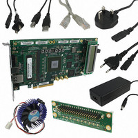
KIT DEV FPGA 2AGX260 W/6.375G TX
Manufacturer
Altera
Series
Arria II GXr
Type
FPGAr
Specifications of DK-DEV-2AGX260N
Contents
Board, Cables, CD, DVD, Power Supply
Silicon Manufacturer
Altera
Core Architecture
FPGA
Core Sub-architecture
Arria
Silicon Core Number
EP2
Silicon Family Name
Arria II GX
Rohs Compliant
Yes
For Use With/related Products
EP2AGX260
Lead Free Status / RoHS Status
Lead free / RoHS Compliant
Other names
544-2696
Available stocks
Company
Part Number
Manufacturer
Quantity
Price
Company:

Part Number:
DK-DEV-2AGX260N
Manufacturer:
Altera
Quantity:
135


2–24
Table 2–23. User-defined Push-button Switch Component Reference and Manufacturing Information
User-Defined DIP Switches
Table 2–24. User-defined DIP Switch Schematic Signal Names and Functions
Table 2–25. User-defined DIP Switch Component Reference and Manufacturing Information
User-Defined LEDs
Arria II GX FPGA Development Board, 6G Edition Reference Manual
Board Reference
Board Reference
Reference
PB1 to PB3
Board
SW2
SW2.1
SW2.2
SW2.3
SW2.4
Four-position DIP switch
User-defined DIP switch connected to
the FPGA device. When the switch is
in the OFF position, a logic 1 is
selected. When the switch is in the
ON position, a logic 0 is selected.
Push-button switch
Table 2–23
manufacturing information.
Board reference SW2 is a 4-pin DIP switch. The switches in SW2 are user-defined and
provided for additional FPGA input control. There is no board-specific function for
these switches.
Table 2–24
corresponding Arria II GX pin numbers.
Table 2–25
manufacturing information.
The development board includes general and HSMC user-defined LEDs. This section
describes all user-defined LEDs. For information on board specific or status LEDs,
refer to
General User-Defined LEDs
Board references D7 through D10 are four user-defined LEDs which allow status and
debugging signals to be driven to the LEDs from the FPGA designs loaded into the
Arria II GX device. The LEDs illuminate when a logic 0 is driven, and turns off when a
logic 1 is driven. There is no board-specific function for these LEDs.
Description
Description
“Status Elements” on page
Description
lists the user-defined push-button switch component reference and the
lists the user-defined DIP switch schematic signal names and their
lists the user-defined DIP switch component reference and the
Dawning Precision Co.
HCH
Manufacturer
Manufacturer
USER_DIP0
USER_DIP1
USER_DIP2
USER_DIP3
Signal Name
2–16.
Schematic
TS-A02SA-2-S100
HPS604-E
Manufacturer
Part Number
Manufacturer
Part Number
I/O Standard
2.5-V
http://www.dawning2.com.tw/
© July 2010 Altera Corporation
Manufacturer Website
Chapter 2: Board Components
Manufacturer Website
www.hchtwn.com.tw
company.php
General User Input/Output
Arria II GX Device
Pin Number
N2
U9
U4
V9
Related parts for DK-DEV-2AGX260N
Image
Part Number
Description
Manufacturer
Datasheet
Request
R

Part Number:
Description:
KIT DEV ARRIA II GX FPGA 2AGX125
Manufacturer:
Altera
Datasheet:

Part Number:
Description:
KIT DEV CYCLONE III LS EP3CLS200
Manufacturer:
Altera
Datasheet:

Part Number:
Description:
KIT DEV STRATIX IV FPGA 4SE530
Manufacturer:
Altera
Datasheet:

Part Number:
Description:
KIT DEV MAX V 5M570Z
Manufacturer:
Altera
Datasheet:

Part Number:
Description:
KIT DEV STRATIX V FPGA 5SGXEA7
Manufacturer:
Altera
Datasheet:

Part Number:
Description:
KIT DEVELOPMENT STRATIX III
Manufacturer:
Altera
Datasheet:

Part Number:
Description:
KIT DEVELOPMENT STRATIX IV
Manufacturer:
Altera
Datasheet:

Part Number:
Description:
KIT DEV ARRIA GX 1AGX60N
Manufacturer:
Altera
Datasheet:
Part Number:
Description:
KIT STARTER CYCLONE IV GX
Manufacturer:
Altera
Datasheet:
Part Number:
Description:
KIT DEVELOPMENT STRATIX IV
Manufacturer:
Altera
Datasheet:

Part Number:
Description:
CPLD, EP610 Family, ECMOS Process, 300 Gates, 16 Macro Cells, 16 Reg., 16 User I/Os, 5V Supply, 35 Speed Grade, 24DIP
Manufacturer:
Altera Corporation
Datasheet:
Part Number:
Description:
CPLD, EP610 Family, ECMOS Process, 300 Gates, 16 Macro Cells, 16 Reg., 16 User I/Os, 5V Supply, 15 Speed Grade, 24DIP
Manufacturer:
Altera Corporation
Datasheet: