AD9956/PCB Analog Devices Inc, AD9956/PCB Datasheet - Page 20
AD9956/PCB
Manufacturer Part Number
AD9956/PCB
Description
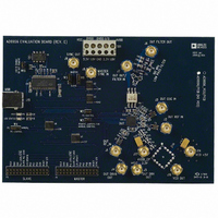
BOARD EVAL FOR AD9956
Manufacturer
Analog Devices Inc
Datasheet
1.AD9956YCPZ.pdf
(32 pages)
Specifications of AD9956/PCB
Module/board Type
Evaluation Board
For Use With/related Products
AD9956
Lead Free Status / RoHS Status
Contains lead / RoHS non-compliant


AD9956
MODES OF OPERATION
DDS MODES OF OPERATION
Single-Tone Mode
This is the default mode of operation for the DDS core. The
phase accumulator runs at a fixed frequency, as per the active
profile’s tuning word. Likewise, any phase offset applied to the
signal is a static value, which comes from the phase offset word
of the active profile. The device has eight different phase/fre-
quency profiles, each with its own 48-bit frequency tuning word
and 14-bit phase offset word. Profiles are selected by applying
their digital value on the profile-select pins (PS2, PS1, and PS0).
It is impossible to use the phase offset of one profile and the
frequency tuning word of another.
Linear Sweep Mode
This mode is entered by setting the linear sweep enable bit in
the control register (CFR1<17> = 1) but leaving the linear
sweep no dwell bit clear (CFR1<16> = 0). When the part is in
linear sweep mode, the frequency accumulator ramps the
output frequency of the device from a programmed lower
frequency to a programmed upper frequency or from the upper
frequency to the lower frequency. The lower frequency is set by the
frequency tuning word stored in Profile 0, and the upper frequency
is set by the frequency tuning word stored in Profile 1.
The combinational logic within the frequency accumulator
requires that the value stored at FTW0 must always be less than
the value stored in FTW. The direction of the sweep (sweep up
to FTW1, sweep down to FTW0) is controlled by the PS0 pin. A
high state on this pin tells the part to sweep up to FTW1. A low
state on this pin tells the part to sweep down to FTW0. The
frequency accumulator requires four values, which are stored in
the register map. First, it requires an incremental frequency
value that tells the frequency accumulator how big of a fre-
quency step to take each time it takes a step when ramping up.
This value is stored in the rising delta frequency tuning word
(RDFTW). The second value required is the rate at which the
frequency accumulator should increment, that is, how often it
should take a step. This value is stored in the rising sweep ramp
rate word (RSRR). The RSRR value specifies the number of
SYNC_CLK cycles the frequency accumulator should count
between steps. The third and fourth values are the falling ramp
equivalents, the falling delta frequency tuning word (FDFTW)
and the falling sweep ramp rate (FSRR).
When operating in the linear sweep default mode, combina-
tional logic ensures that the part never ramps up past FTW1,
even if the next RDFTW increments the frequency past FTW1.
Once it reaches FTW1, as long as the PS0 pin stays high, the
frequency remains at FTW1. Likewise, the internal logic ensures
that the part never ramps down past FTW0, even if the next
RDFTW increments the frequency past FTW0. During a sweep
down (PS0 = 0), once the part reaches FTW0, as long as the PS0
pin stays low, the frequency remains at FTW0.
Rev. A | Page 20 of 32
If a sweep is interrupted and the state of the PS0 pin is changed
during the midst of a sweep, the part begins sweeping in the
new direction at the rate dictated by the relevant delta fre-
quency tuning word and sweep ramp rate word. For example, if
the part is programmed to sweep from 100 MHz to 140 MHz
and to take 1 kHz steps every 1000 sync clock cycles (rising and
falling sweep words are the same), it would take four seconds to
complete a sweep. If the PS0 has been low for a very long time
(more than four seconds), changing the PS0 pin to high starts a
sweep up to 140 MHz. If after two seconds (not enough time for
a full sweep in this example) the PS0 pin is brought low again,
the part begins sweeping down from the current value, roughly
120 MHz.
Linear Sweep No Dwell Mode
This mode is entered by setting the linear sweep enable bit and
the linear sweep no dwell bit in the control register
(CFR<17:16> =1). When the part is in linear sweep no dwell
mode, the frequency accumulator ramps the output frequency
of the device from a programmed lower frequency to a pro-
grammed upper frequency. Upon reaching the upper frequency,
the accumulator returns to the lower frequency directly, without
ramping back down. Unlike the default mode of the linear
sweep, this mode uses only the rising delta frequency tuning
word (RDFTW) and the rising sweep ramp rate (RSRR). The
operation is still controlled by the PS0 pin. In this mode, how-
ever, it acts as a trigger for the sweep, not a direction bit. Once a
PS0 low-to-high transition is detected, the part completes the
entire sweep, regardless of whether or not the PS0 pin is
changed back to low during the sweep. After the sweep is com-
pleted, another sweep may be initiated by applying another
rising edge on the PS0 pin. This means that the PS0 pin needs to
be brought low prior to the next sweep.
SYNCHRONIZATION MODES FOR MULTIPLE DEVICES
In a DDS system, the SYNC_CLK is derived internally off the
master system clock, SYSCLK, with a ÷4 divider. Because the
divider does not power up to a known state, it is possible for
multiple devices in a system to have staggered clock-phase
relationships. This is because each device could potentially gen-
erate the SYNC_CLK rising edge from any one of four rising
edges of SYSCLK. This ambiguity can be resolved by employing
digital synchronization logic to control the phase relationships
of the derived clocks among different devices in the system. It is
important to note that the synchronization functions included
on the AD9956 control only the timing relationships among
different digital clocks. They do not compensate for the analog
timing skew on the system clock due to mismatched phase
relationships on the input clock, REFCLK. Figure 28 illustrates
this concept.
Related parts for AD9956/PCB
Image
Part Number
Description
Manufacturer
Datasheet
Request
R

Part Number:
Description:
400 Msps 14 Bit DDS EvBd. W/2450MHz VCO
Manufacturer:
Analog Devices Inc
Datasheet:
Part Number:
Description:
400 Msps 14 Bit DDS Eval Bd.
Manufacturer:
Analog Devices Inc
Datasheet:
Part Number:
Description:
BOARD EVAL 14BIT 1.8V 48LFCSP
Manufacturer:
Analog Devices Inc
Datasheet:


Part Number:
Description:
±1.7g Dual-Axis IMEMS Accelerometer Evaluation Board
Manufacturer:
Analog Devices Inc
Datasheet:
Part Number:
Description:
Inertial Sensor Evaluation System
Manufacturer:
Analog Devices Inc
Datasheet:
Part Number:
Description:
Manufacturer:
Analog Devices Inc
Datasheet:
Part Number:
Description:
Manufacturer:
Analog Devices Inc
Datasheet:
Part Number:
Description:
Manufacturer:
Analog Devices Inc
Datasheet:
Part Number:
Description:
Manufacturer:
Analog Devices Inc
Datasheet:
Part Number:
Description:
Manufacturer:
Analog Devices Inc
Datasheet:
Part Number:
Description:
Manufacturer:
Analog Devices Inc
Datasheet:
Part Number:
Description:
Manufacturer:
Analog Devices Inc
Datasheet: