AD9956/PCB Analog Devices Inc, AD9956/PCB Datasheet - Page 21
AD9956/PCB
Manufacturer Part Number
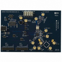
AD9956/PCB
Description
BOARD EVAL FOR AD9956
Manufacturer
Analog Devices Inc
Datasheet
1.AD9956YCPZ.pdf
(32 pages)
Specifications of AD9956/PCB
Module/board Type
Evaluation Board
For Use With/related Products
AD9956
Lead Free Status / RoHS Status
Contains lead / RoHS non-compliant


Automatic Synchronization
In automatic synchronization mode, the device is placed into
slave mode and automatically aligns the internal SYNC_CLK to
a master SYNC_CLK signal, supplied on the SYNC_IN input.
When this bit is enabled, the PLL_LOCK is not available as an
output, however, an out-of-lock condition can be detected by
reading Control Function Register 1 and checking the status of
the PLL_LOCK_ERROR bit, CFR1<24>. The automatic
synchronization function is enabled by setting the Control
Function Register 1 automatic synchronization bit, CFR1<3>.
To employ this function at higher clock rates (SYNC_CLK >
62.5 MHz and SYSCLK > 250 MHz), the high speed sync
enable bit (CFR1<0>) should be set as well.
Manual Synchronization, Hardware Controlled
In this mode, the user controls the timing relationship of the
SYNC_CLK with respect to SYSCLK. When hardware manual
synchronization is enabled, the PLL_LOCK/ SYNC_IN pin
becomes a digital input. For each and every rising edge detected
on the SYNC_IN input, the device advances the SYNC_IN
rising edge by one SYSCLK period. When this bit is enabled, the
PLL_LOCK is not available as an output. However, an out-of-
lock condition can be detected by reading Control Function
Register 1 and checking the status of the PLL Lock Error bit,
CFR1<24>. This synchronization function is enabled by setting
the hardware manual synchronization enable bit, CFR1<1>.
Rev. A | Page 21 of 32
Manual Synchronization, Software Controlled
In this mode, the user controls the timing relationship between
SYNC_CLK and SYSCLK through software programming.
When the software manual synchronization bit (CFR1<2>) is
set high, the SYNC_CLK is advanced by one SYSCLK cycle.
Once this operation is complete, the bit is cleared. The user can
set this bit repeatedly to advance the SYNC_CLK rising edge
multiple times. Because the operation does not use the
PLL_LOCK/ SYNC_IN pin as a SYNC_IN input, the
PLL_LOCK signal can be monitored on the PLL_LOCK pin
during this operation.
Figure 28. Synchronization Functions: Capabilities and Limitations
SYNC CLK DUT2 WITHOUT
RELATIONSHIPS, THEY CANNOT DESKEW THE EDGES OF CLOCKS
SYNC CLK DUT2 WITH
SYNC_CLK ALIGNED
SYNC_CLK ALIGNED
SYNCHRONIZATION FUNCTIONS CAN ALIGN DIGITAL CLOCK
SYSCLK DUT 1
SYSCLK DUT 2
SYNC CLK
DUT1
0
3
1
0
2
1
3
2
0
AD9956
3
Related parts for AD9956/PCB
Image
Part Number
Description
Manufacturer
Datasheet
Request
R

Part Number:
Description:
400 Msps 14 Bit DDS EvBd. W/2450MHz VCO
Manufacturer:
Analog Devices Inc
Datasheet:
Part Number:
Description:
400 Msps 14 Bit DDS Eval Bd.
Manufacturer:
Analog Devices Inc
Datasheet:
Part Number:
Description:
BOARD EVAL 14BIT 1.8V 48LFCSP
Manufacturer:
Analog Devices Inc
Datasheet:


Part Number:
Description:
±1.7g Dual-Axis IMEMS Accelerometer Evaluation Board
Manufacturer:
Analog Devices Inc
Datasheet:
Part Number:
Description:
Inertial Sensor Evaluation System
Manufacturer:
Analog Devices Inc
Datasheet:
Part Number:
Description:
Manufacturer:
Analog Devices Inc
Datasheet:
Part Number:
Description:
Manufacturer:
Analog Devices Inc
Datasheet:
Part Number:
Description:
Manufacturer:
Analog Devices Inc
Datasheet:
Part Number:
Description:
Manufacturer:
Analog Devices Inc
Datasheet:
Part Number:
Description:
Manufacturer:
Analog Devices Inc
Datasheet:
Part Number:
Description:
Manufacturer:
Analog Devices Inc
Datasheet:
Part Number:
Description:
Manufacturer:
Analog Devices Inc
Datasheet: