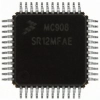
MC908SR12MFAE Freescale Semiconductor, MC908SR12MFAE Datasheet - Page 215

MC908SR12MFAE
Manufacturer Part Number
MC908SR12MFAE
Description
IC MCU 12K FLASH 8MHZ 48-LQFP
Manufacturer
Freescale Semiconductor
Series
HC08r
Datasheet
1.MC908SR12MFAE.pdf
(404 pages)
Specifications of MC908SR12MFAE
Core Processor
HC08
Core Size
8-Bit
Speed
8MHz
Connectivity
I²C, SCI
Peripherals
LVD, POR, PWM, Temp Sensor
Number Of I /o
31
Program Memory Size
12KB (12K x 8)
Program Memory Type
FLASH
Ram Size
512 x 8
Voltage - Supply (vcc/vdd)
4.5 V ~ 5.5 V
Data Converters
A/D 14x10b
Oscillator Type
Internal
Operating Temperature
-40°C ~ 125°C
Package / Case
48-LQFP
Lead Free Status / RoHS Status
Lead free / RoHS Compliant
Eeprom Size
-
Available stocks
Company
Part Number
Manufacturer
Quantity
Price
Company:
Part Number:
MC908SR12MFAE
Manufacturer:
Freescale Semiconductor
Quantity:
10 000
Company:
Part Number:
MC908SR12MFAER
Manufacturer:
Freescale Semiconductor
Quantity:
10 000
- Current page: 215 of 404
- Download datasheet (2Mb)
13.5 PWM Automatic Phase Control
MC68HC908SR12•MC68HC08SR12 — Rev. 5.0
Freescale Semiconductor
PWM2
PWM1
PWM0
256 × T
PHASE VALUE 1
The automatic phase control function allows precise phase difference
between the PWM output signals.
Figure 13-4
Use the following steps to generate phase difference on PWM channels:
When phase control is enabled, the PWM2 counter will start counting
immediately, but the PWM1 and PWM0 counters will be held at zero.
After the PWM2 counter reaches the phase value, PH[0:6], the PWM1
counter is released and starts counting. Finally, when the PMW1 counter
reaches the phase value, PH[0:6], PWM0 is released and starts
counting. It is possible to change the value of PH[0:6] after the PWM1
counter has started and before the start of the PWM0 counter. This way,
difference phases can be set between PWM2 and PWM1; PWM1 and
PWM0.
Figure 13-4. PWM Automatic Phase Control
1. Clear PWM enable bits, PWMEN[0:2], to logic 0.
2. Write delay value in PHD[0:6].
3. Set PWM automatic phase control enable bit, PHEN, to logic 1.
4. Set the PWM channel enable bits, PCH[0:2], to logic 1.
5. Set the PWM enable bits, PWMEN[0:2], to logic 1, to enable the
PWM counters.
PHASE VALUE 2
Pulse Width Modulator (PWM)
shows the phase delays between the PWM output signals.
256 × T
256 × T
256 × T
PWM Automatic Phase Control
Pulse Width Modulator (PWM)
Data Sheet
215
Related parts for MC908SR12MFAE
Image
Part Number
Description
Manufacturer
Datasheet
Request
R
Part Number:
Description:
Manufacturer:
Freescale Semiconductor, Inc
Datasheet:
Part Number:
Description:
Manufacturer:
Freescale Semiconductor, Inc
Datasheet:
Part Number:
Description:
Manufacturer:
Freescale Semiconductor, Inc
Datasheet:
Part Number:
Description:
Manufacturer:
Freescale Semiconductor, Inc
Datasheet:
Part Number:
Description:
Manufacturer:
Freescale Semiconductor, Inc
Datasheet:
Part Number:
Description:
Manufacturer:
Freescale Semiconductor, Inc
Datasheet:
Part Number:
Description:
Manufacturer:
Freescale Semiconductor, Inc
Datasheet:
Part Number:
Description:
Manufacturer:
Freescale Semiconductor, Inc
Datasheet:
Part Number:
Description:
Manufacturer:
Freescale Semiconductor, Inc
Datasheet:
Part Number:
Description:
Manufacturer:
Freescale Semiconductor, Inc
Datasheet:
Part Number:
Description:
Manufacturer:
Freescale Semiconductor, Inc
Datasheet:
Part Number:
Description:
Manufacturer:
Freescale Semiconductor, Inc
Datasheet:
Part Number:
Description:
Manufacturer:
Freescale Semiconductor, Inc
Datasheet:
Part Number:
Description:
Manufacturer:
Freescale Semiconductor, Inc
Datasheet:
Part Number:
Description:
Manufacturer:
Freescale Semiconductor, Inc
Datasheet:


