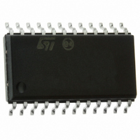
ST72F63BE2M1 STMicroelectronics, ST72F63BE2M1 Datasheet - Page 162

ST72F63BE2M1
Manufacturer Part Number
ST72F63BE2M1
Description
MCU 8BIT LS USB 8KB FLASH 24SOIC
Manufacturer
STMicroelectronics
Series
ST7r
Datasheet
1.ST72F63BD6U1TR.pdf
(186 pages)
Specifications of ST72F63BE2M1
Core Processor
ST7
Core Size
8-Bit
Speed
8MHz
Connectivity
I²C, SCI, USB
Peripherals
DMA, LVD, POR, PWM, WDT
Number Of I /o
14
Program Memory Size
8KB (8K x 8)
Program Memory Type
FLASH
Ram Size
1K x 8
Voltage - Supply (vcc/vdd)
4 V ~ 5.5 V
Oscillator Type
Internal
Operating Temperature
0°C ~ 70°C
Package / Case
24-SOIC (7.5mm Width)
Data Converters
A/D 12x10b
Processor Series
ST72F6x
Core
ST7
Data Bus Width
8 bit
Data Ram Size
384 B
Interface Type
I2C, SCI
Maximum Clock Frequency
8 MHz
Number Of Programmable I/os
14
Number Of Timers
1
Maximum Operating Temperature
+ 70 C
Mounting Style
SMD/SMT
Development Tools By Supplier
ST7MDTU3-EPB/US, ST7MDTULS-EVAL, ST72F63B-SK/RAIS, ST7MDTU3-EMU3, STX-RLINK
Minimum Operating Temperature
0 C
For Use With
497-8209 - BOARD EVAL USB STUSB02E/ST72F63B497-8208 - BOARD EVAL USB STUSB03E/ST72F63B497-5521 - EVAL BOARD LOW SPEED USB497-5046 - KIT TOOL FOR ST7/UPSD/STR7 MCU
Lead Free Status / RoHS Status
Lead free / RoHS Compliant
Eeprom Size
-
Lead Free Status / Rohs Status
Details
Other names
497-5624-5
Available stocks
Company
Part Number
Manufacturer
Quantity
Price
Electrical characteristics
Table 77.
1. Legend: R
2. The above variations depend on the accuracy of the external components used.
3. For speeds around 200 kHz, achieved speed can have ±5% tolerance.
4. For other speed ranges, achieved speed can have ±2% tolerance.
13.11
162/186
400
300
200
100
50
20
(kHz)
f
SCL
NA
NA
83h
10h
24h
5Fh
R
P
P
Table 77
SCL line frequency.
SCL frequency
8-bit ADC
Subject to general operating conditions for V
Table 78.
1. Unless otherwise specified, typical data are based on T
2. When V
3. Any added external serial resistor will downgrade the ADC accuracy (especially for resistance greater than
4. The stabilization time of the AD converter is masked by the first t
= External pull-up resistance; f
=3.3 kΩ R
Symbol
C
t
R
f
V
t
STAB
ADC
ADC
10k
is then always valid.
ADC
V
AIN
AIN
DD
Ω
). Data based on characterization results, not tested in production.
= 4.1 V
gives the values to be written in the I2CCCR register to obtain the required I
NA
NA
83h
10h
24h
5Fh
ADC clock frequency
Conversion range voltage
External input resistor
Internal sample and hold
capacitor
Stabilization time after ADC
enable
Conversion time (Sample+Hold)
- Sample capacitor loading time
- Hold conversion time
DDA
P
=4.7 kΩ R
8-bit ADC characteristics
and V
f
(1)(2)(3)(4)
CPU
SSA
=4 MHz
Parameter
pins are not available on the pinout, the ADC refer to V
NA
NA
83h
10h
24h
5Fh
P
=3.3 kΩ R
SCL
= I
V
DD
2
C speed; NA = not achievable.
Doc ID 7516 Rev 8
= 5 V
(2)
NA
NA
83h
10h
24h
5Fh
P
=4.7 kΩ R
I2CCCR Value
f
f
CPU
ADC
Conditions
DD
=8 MHz,
=2 MHz
83h
85h
24h
4Ch
FFh
8Ah
P
, f
A
=3.3 kΩ R
=25°C and V
OSC
V
DD
, and T
LOAD
= 4.1 V
83
85h
89h
23h
4Ch
FFh
. The first conversion after the enable
P
DD
A
=4.7 kΩ R
V
Min
-V
SSA
unless otherwise specified.
-
-
-
f
SS
CPU
=5V.
DD
=8 MHz
Typ
and V
83h
85h
8Ah
24h
4Ch
FFh
0
6
-
-
-
6
4
8
(4)
P
(1)
=3.3 kΩ R
SS.
V
V
DD
10
Max
DDA
4
-
(3)
= 5 V
ST7263Bxx
83h
85h
8Ah
23h
4Ch
FFh
P
=4.7 kΩ
1/f
2
MHz
Unit
κΩ
pF
C
µs
V
ADC


