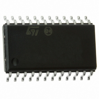
ST72F63BE2M1 STMicroelectronics, ST72F63BE2M1 Datasheet - Page 25

ST72F63BE2M1
Manufacturer Part Number
ST72F63BE2M1
Description
MCU 8BIT LS USB 8KB FLASH 24SOIC
Manufacturer
STMicroelectronics
Series
ST7r
Datasheet
1.ST72F63BD6U1TR.pdf
(186 pages)
Specifications of ST72F63BE2M1
Core Processor
ST7
Core Size
8-Bit
Speed
8MHz
Connectivity
I²C, SCI, USB
Peripherals
DMA, LVD, POR, PWM, WDT
Number Of I /o
14
Program Memory Size
8KB (8K x 8)
Program Memory Type
FLASH
Ram Size
1K x 8
Voltage - Supply (vcc/vdd)
4 V ~ 5.5 V
Oscillator Type
Internal
Operating Temperature
0°C ~ 70°C
Package / Case
24-SOIC (7.5mm Width)
Data Converters
A/D 12x10b
Processor Series
ST72F6x
Core
ST7
Data Bus Width
8 bit
Data Ram Size
384 B
Interface Type
I2C, SCI
Maximum Clock Frequency
8 MHz
Number Of Programmable I/os
14
Number Of Timers
1
Maximum Operating Temperature
+ 70 C
Mounting Style
SMD/SMT
Development Tools By Supplier
ST7MDTU3-EPB/US, ST7MDTULS-EVAL, ST72F63B-SK/RAIS, ST7MDTU3-EMU3, STX-RLINK
Minimum Operating Temperature
0 C
For Use With
497-8209 - BOARD EVAL USB STUSB02E/ST72F63B497-8208 - BOARD EVAL USB STUSB03E/ST72F63B497-5521 - EVAL BOARD LOW SPEED USB497-5046 - KIT TOOL FOR ST7/UPSD/STR7 MCU
Lead Free Status / RoHS Status
Lead free / RoHS Compliant
Eeprom Size
-
Lead Free Status / Rohs Status
Details
Other names
497-5624-5
Available stocks
Company
Part Number
Manufacturer
Quantity
Price
ST7263Bxx
4.3.1
4.4
Readout protection
Readout protection, when selected, provides a protection against program memory content
extraction and against write access to Flash memory. Even if no protection can be
considered as totally unbreakable, the feature provides a very high level of protection for a
general purpose microcontroller.
In Flash devices, this protection is removed by reprogramming the option. In this case, the
entire program memory is first automatically erased and the device can be reprogrammed.
Readout protection selection depends on the device type:
●
●
Figure 8.
ICC interface
ICC (In-circuit communication) needs a minimum of four and up to six pins to be connected
to the programming tool (see
●
●
●
●
●
●
●
DFFFh
BFFFh
D7FFh
EFFFh
FFFFh
3FFFh
7FFFh
9FFFh
1000h
In Flash devices it is enabled and removed through the FMP_R bit in the option byte.
In ROM devices it is enabled by mask option specified in the Option List.
RESET: device reset
V
ICCCLK: ICC output serial clock pin
ICCDATA: ICC input/output serial data pin
ICCSEL/V
OSC1(or OSCIN): main clock input for external source (optional)
V
SS
DD
: device power supply ground
: application board power supply (see
4K
Memory map and sector address
PP
: programming voltage
8K
2 Kbytes
10K
Figure
Doc ID 7516 Rev 8
8 Kbytes
16K
9). These pins are:
4 Kbytes
4 Kbytes
16 Kbytes
24K
Figure
24 Kbytes
32K
9, Note 3)
40 Kbytes 52 Kbytes
48K
Flash program memory
60K
FLASH
MEMORY SIZE
SECTOR 2
SECTOR 1
SECTOR 0
25/186


