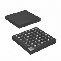
ATXMEGA32A4-CUR Atmel, ATXMEGA32A4-CUR Datasheet - Page 133

ATXMEGA32A4-CUR
Manufacturer Part Number
ATXMEGA32A4-CUR
Description
MCU AVR 32+4 FLASH 49VFBGA
Manufacturer
Atmel
Series
AVR® XMEGAr
Specifications of ATXMEGA32A4-CUR
Core Processor
AVR
Core Size
8/16-Bit
Speed
32MHz
Connectivity
I²C, IrDA, SPI, UART/USART
Peripherals
Brown-out Detect/Reset, DMA, POR, PWM, WDT
Number Of I /o
34
Program Memory Size
32KB (16K x 16)
Program Memory Type
FLASH
Eeprom Size
2K x 8
Ram Size
4K x 8
Voltage - Supply (vcc/vdd)
1.6 V ~ 3.6 V
Data Converters
A/D 12x12b, D/A 2x12b
Oscillator Type
Internal
Operating Temperature
-40°C ~ 85°C
Package / Case
49-VFBGA
For Use With
ATAVRONEKIT - KIT AVR/AVR32 DEBUGGER/PROGRMMRATSTK600 - DEV KIT FOR AVR/AVR32770-1007 - ISP 4PORT ATMEL AVR MCU SPI/JTAG770-1004 - ISP 4PORT FOR ATMEL AVR MCU SPI
Lead Free Status / RoHS Status
Lead free / RoHS Compliant
Available stocks
Company
Part Number
Manufacturer
Quantity
Price
- Current page: 133 of 445
- Download datasheet (6Mb)
13.4.4
13.5
8077H–AVR–12/09
Reading the Pin value
Wired-AND
Figure 13-6. Output configuration - Wired-OR with optional pull-down.
With Wired-AND configuration, the pin will be driven low when the corresponding bit in OUT is
written to zero. When OUT is set to one, the pin is released allowing the pin to be pulled low with
the internal or an external pull-resistor. If internal pull-up is used, this is also active if the pin is
set as input.
Figure 13-7. Output configuration - Wired-AND with optional pull-up.
Independent of the pin data direction, the pin value can be read from the IN register as shown in
Figure 13-1 on page
register bit and the preceding flip-flop constitute a synchronizer. The synchronizer is needed to
avoid metastability if the physical pin changes value near the edge of the internal clock. The
Synchronizer introduces a delay on the internal signal line.
timing diagram of the synchronization when reading an externally applied pin value. The maxi-
mum and minimum propagation delays are denoted t
130. If the digital input is disabled, the pin value cannot be read. The IN
OUTn
OUTn
INn
INn
pd,max
and t
Figure 13-8 on page 134
pd,min
respectively.
Pn
Pn
XMEGA A
shows a
133
Related parts for ATXMEGA32A4-CUR
Image
Part Number
Description
Manufacturer
Datasheet
Request
R

Part Number:
Description:
DEV KIT FOR AVR/AVR32
Manufacturer:
Atmel
Datasheet:

Part Number:
Description:
INTERVAL AND WIPE/WASH WIPER CONTROL IC WITH DELAY
Manufacturer:
ATMEL Corporation
Datasheet:

Part Number:
Description:
Low-Voltage Voice-Switched IC for Hands-Free Operation
Manufacturer:
ATMEL Corporation
Datasheet:

Part Number:
Description:
MONOLITHIC INTEGRATED FEATUREPHONE CIRCUIT
Manufacturer:
ATMEL Corporation
Datasheet:

Part Number:
Description:
AM-FM Receiver IC U4255BM-M
Manufacturer:
ATMEL Corporation
Datasheet:

Part Number:
Description:
Monolithic Integrated Feature Phone Circuit
Manufacturer:
ATMEL Corporation
Datasheet:

Part Number:
Description:
Multistandard Video-IF and Quasi Parallel Sound Processing
Manufacturer:
ATMEL Corporation
Datasheet:

Part Number:
Description:
High-performance EE PLD
Manufacturer:
ATMEL Corporation
Datasheet:

Part Number:
Description:
8-bit Flash Microcontroller
Manufacturer:
ATMEL Corporation
Datasheet:

Part Number:
Description:
2-Wire Serial EEPROM
Manufacturer:
ATMEL Corporation
Datasheet:


