ATXMEGA32A4-CUR Atmel, ATXMEGA32A4-CUR Datasheet - Page 199
ATXMEGA32A4-CUR
Manufacturer Part Number
ATXMEGA32A4-CUR
Description
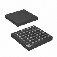
MCU AVR 32+4 FLASH 49VFBGA
Manufacturer
Atmel
Series
AVR® XMEGAr
Specifications of ATXMEGA32A4-CUR
Core Processor
AVR
Core Size
8/16-Bit
Speed
32MHz
Connectivity
I²C, IrDA, SPI, UART/USART
Peripherals
Brown-out Detect/Reset, DMA, POR, PWM, WDT
Number Of I /o
34
Program Memory Size
32KB (16K x 16)
Program Memory Type
FLASH
Eeprom Size
2K x 8
Ram Size
4K x 8
Voltage - Supply (vcc/vdd)
1.6 V ~ 3.6 V
Data Converters
A/D 12x12b, D/A 2x12b
Oscillator Type
Internal
Operating Temperature
-40°C ~ 85°C
Package / Case
49-VFBGA
For Use With
ATAVRONEKIT - KIT AVR/AVR32 DEBUGGER/PROGRMMRATSTK600 - DEV KIT FOR AVR/AVR32770-1007 - ISP 4PORT ATMEL AVR MCU SPI/JTAG770-1004 - ISP 4PORT FOR ATMEL AVR MCU SPI
Lead Free Status / RoHS Status
Lead free / RoHS Compliant
Available stocks
Company
Part Number
Manufacturer
Quantity
Price


18.3.2
18.3.3
SYNCCTRL - Synchronisation Control/Status Register
INTCTRL - Interrupt Control Register
• Bit 0 - ENABLE: RTC Enable
Setting this bit enables the RTC. The synchronization time between the RTC and the System
Clock domains is one half RTC clock cycle from writing the register and until this has effect in
RTC clock domain, i.e until the RTC starts.
For the RTC to start running the PER Register must also be set to a different value that zero.
• Bits 7:5 - Reserved
These bits are unused and reserved for future use. For compatibility with future devices, always
write these bits to zero when this register is written.
• Bit 4- SYNCCNT: Enable Synchronization of the CNT register
Setting this bit will start synchronization of CNT register from the RTC clock to the System Clock
domain. The bit is automatically cleared when synchronization is done.
• Bits 3:1 - Reserved
These bits are unused and reserved for future use. For compatibility with future devices, always
write these bits to zero when this register is written.
• Bit 0 - SYNCBUSY: RTC Synchronization Busy Flag
This flag is set when the CTRL or CNT registers are busy synchronizing from the System Clock
to the RTC clock domain. The CTRL register synchronization is triggered when it is written. The
CNT register are synchronized when the most significant byte of the register is written.
• Bits 7:4 - Reserved
These bits are unused and reserved for future use. For compatibility with future devices, always
write these bits to zero when this register is written.
• Bits 3:2 - COMPINTLVL[1:0]: RTC Compare Match Interrupt Enable
These bits enable the RTC Compare Match Interrupt and select the interrupt level as described
in
enabled interrupt will trigger when the COMPIF in the INTFLAGS register is set.
Bit
+0x01
Read/Write
Reset Value
Bit
+0x02
Read/Write
Reset Value
Section 12. ”Interrupts and Programmable Multi-level Interrupt Controller” on page
7
-
R
0
7
-
R
0
6
-
R
0
6
-
R
0
5
-
R
0
5
-
R
0
SYNCCNT
R/W
4
0
4
-
R
0
COMPINTLVL[1:0]
R/W
3
3
-
R
0
0
R/W
2
2
-
R
0
0
R/W
1
1
-
R
0
0
OCINTLVL[1:0]
SYNCBUSY
R/W
R/W
0
0
0
0
SYNCCTRL
INTCTRL
123. The
Related parts for ATXMEGA32A4-CUR
Image
Part Number
Description
Manufacturer
Datasheet
Request
R

Part Number:
Description:
DEV KIT FOR AVR/AVR32
Manufacturer:
Atmel
Datasheet:

Part Number:
Description:
INTERVAL AND WIPE/WASH WIPER CONTROL IC WITH DELAY
Manufacturer:
ATMEL Corporation
Datasheet:
Part Number:
Description:
Low-Voltage Voice-Switched IC for Hands-Free Operation
Manufacturer:
ATMEL Corporation
Datasheet:
Part Number:
Description:
MONOLITHIC INTEGRATED FEATUREPHONE CIRCUIT
Manufacturer:
ATMEL Corporation
Datasheet:
Part Number:
Description:
AM-FM Receiver IC U4255BM-M
Manufacturer:
ATMEL Corporation
Datasheet:
Part Number:
Description:
Monolithic Integrated Feature Phone Circuit
Manufacturer:
ATMEL Corporation
Datasheet:
Part Number:
Description:
Multistandard Video-IF and Quasi Parallel Sound Processing
Manufacturer:
ATMEL Corporation
Datasheet:
Part Number:
Description:
High-performance EE PLD
Manufacturer:
ATMEL Corporation
Datasheet:
Part Number:
Description:
8-bit Flash Microcontroller
Manufacturer:
ATMEL Corporation
Datasheet:
Part Number:
Description:
2-Wire Serial EEPROM
Manufacturer:
ATMEL Corporation
Datasheet: