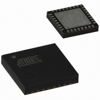
AT89C5131A-PUTUM Atmel, AT89C5131A-PUTUM Datasheet - Page 70

AT89C5131A-PUTUM
Manufacturer Part Number
AT89C5131A-PUTUM
Description
IC 8051 MCU FLASH 32K USB 32QFN
Manufacturer
Atmel
Series
AT89C513xr
Datasheet
1.AT89C5130A-PUTUM.pdf
(188 pages)
Specifications of AT89C5131A-PUTUM
Core Processor
C52X2
Core Size
8-Bit
Speed
48MHz
Connectivity
I²C, SPI, UART/USART, USB
Peripherals
LED, POR, PWM, WDT
Number Of I /o
18
Program Memory Size
32KB (32K x 8)
Program Memory Type
FLASH
Eeprom Size
4K x 8
Ram Size
1.25K x 8
Voltage - Supply (vcc/vdd)
2.7 V ~ 5.5 V
Oscillator Type
Internal
Operating Temperature
-40°C ~ 85°C
Package / Case
32-VQFN Exposed Pad, 32-HVQFN, 32-SQFN, 32-DHVQFN
Core
8051
Processor Series
AT89x
Data Bus Width
8 bit
Maximum Clock Frequency
48 MHz
Data Ram Size
1.25 KB
Number Of Programmable I/os
34
Number Of Timers
16 bit
Operating Supply Voltage
2.7 V to 5.5 V
Mounting Style
SMD/SMT
Height
0.95 mm
Interface Type
2-Wire, EUART, SPI, USB
Length
7 mm
Maximum Operating Temperature
+ 85 C
Minimum Operating Temperature
- 40 C
Supply Voltage (max)
5.5 V
Supply Voltage (min)
2.7 V
Width
7 mm
For Use With
AT89OCD-01 - USB EMULATOR FOR AT8XC51 MCUAT89STK-10 - KIT EVAL APPL MASS STORAGEAT89STK-05 - KIT STARTER FOR AT89C5131
Lead Free Status / RoHS Status
Lead free / RoHS Compliant
Data Converters
-
Lead Free Status / Rohs Status
Details
Available stocks
Company
Part Number
Manufacturer
Quantity
Price
Part Number:
AT89C5131A-PUTUM
Manufacturer:
ATMEL/爱特梅尔
Quantity:
20 000
15.2
15.2.1
70
Automatic Address Recognition
AT89C5130A/31A-M
Given Address
Figure 15-3. UART Timings in Modes 2 and 3
The automatic address recognition feature is enabled when the multiprocessor communication
feature is enabled (SM2 bit in SCON register is set).
Implemented in hardware, automatic address recognition enhances the multiprocessor commu-
nication feature by allowing the serial port to examine the address of each incoming command
frame. Only when the serial port recognizes its own address, the receiver sets RI bit in SCON
register to generate an interrupt. This ensures that the CPU is not interrupted by command
frames addressed to other devices.
If desired, you may enable the automatic address recognition feature in mode 1. In this configu-
ration, the stop bit takes the place of the ninth data bit. Bit RI is set only when the received
command frame address matches the device’s address and is terminated by a valid stop bit.
To support automatic address recognition, a device is identified by a given address and a broad-
cast address.
Note:
Each device has an individual address that is specified in SADDR register; the SADEN register
is a mask byte that contains don’t care bits (defined by zeros) to form the device’s given
address. The don’t care bits provide the flexibility to address one or more slaves at a time. The
following example illustrates how a given address is formed.
To address a device by its individual address, the SADEN mask byte must be 1111 1111b.
For example:
The following is an example of how to use given addresses to address different slaves:
Slave A:SADDR1111 0001b
Slave B:SADDR1111 0011b
SADDR0101 0110b
SADEN1111 1100b
Given0101 01XXb
SADEN1111 1010b
Given1111 0X0Xb
SADEN1111 1001b
Given1111 0XX1b
The multiprocessor communication and automatic address recognition features cannot be
enabled in mode 0 (i.e., setting SM2 bit in SCON register in mode 0 has no effect).
SMOD0 = 0
SMOD0 = 1
SMOD0 = 1
RXD
FE
RI
RI
Start
Bit
D0
D1
D2
D3
Data Byte
D4
D5
D6
D7
Ninth
D8
Bit
Stop
Bit
4337K–USB–04/08


