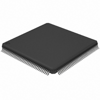
LH75411N0Q100C0;55 NXP Semiconductors, LH75411N0Q100C0;55 Datasheet - Page 30

LH75411N0Q100C0;55
Manufacturer Part Number
LH75411N0Q100C0;55
Description
IC ARM7 BLUESTREAK MCU 144LQFP
Manufacturer
NXP Semiconductors
Series
BlueStreak ; LH7r
Datasheet
1.LH75401N0Q100C055.pdf
(63 pages)
Specifications of LH75411N0Q100C0;55
Package / Case
144-LQFP
Core Processor
ARM7
Core Size
16/32-Bit
Speed
84MHz
Connectivity
EBI/EMI, SPI, SSI, SSP, UART/USART
Peripherals
Brown-out Detect/Reset, DMA, LCD, POR, PWM, WDT
Number Of I /o
76
Program Memory Type
ROMless
Ram Size
32K x 8
Voltage - Supply (vcc/vdd)
1.7 V ~ 3.6 V
Data Converters
A/D 8x10b
Oscillator Type
External
Operating Temperature
-40°C ~ 85°C
Processor Series
LH75
Core
ARM7TDMI-S
Data Bus Width
32 bit
Data Ram Size
32 KB
Interface Type
JTAG, SPI, UART
Maximum Clock Frequency
84 MHz
Number Of Programmable I/os
76
Number Of Timers
3
Operating Supply Voltage
3.3 V
Maximum Operating Temperature
+ 85 C
Mounting Style
SMD/SMT
3rd Party Development Tools
MDK-ARM, RL-ARM, ULINK2
Minimum Operating Temperature
- 40 C
On-chip Adc
10 bit, 8 Channel
Lead Free Status / RoHS Status
Lead free / RoHS Compliant
Eeprom Size
-
Program Memory Size
-
Lead Free Status / Rohs Status
Lead free / RoHS Compliant
Other names
568-4330
935285046557
935285046557
LH75401/LH75411
Watchdog Timer (WDT)
allows a selectable time-out interval to detect malfunc-
tions. The timer must be reset by software periodically.
Otherwise, a time-out occurs, interrupting the system.
If the interrupt is not serviced within the timeout period,
the WDT triggers the RCPC to generate a System
Reset. If the WDT times out, it sets a bit in the RCPC
Reset Status Register.
a time-out of 216 through 231 system clock cycles. All
Control and Status Registers for the Watchdog Timer
are accessed through the APB.
30
Motorola SPI
SSI
National Semiconductor
Microwire
The WDT consists of a 32-bit down-counter that
The WDT supports 16 selectable time intervals, for
MODE
For communications with Motorola SPI-compatible
devices. Clock polarity and phase are programmable.
For communications with Texas Instruments DSP-
compatible Serial Synchronous Interface devices.
For communications with National Semiconductor
Microwire-compatible devices.
NXP Semiconductors
Rev. 01 — 16 July 2007
Table 10. SSP Modes
DESCRIPTION
WDT FEATURES
• Counter generates an interrupt at a set interval and
• Default timeout period is set to the minimum timeout
• WDT is driven by the APB.
• Built-in protection mechanism guards against
• WDT can be programmed to trigger a System Reset
• WDT can be programmed to trigger an interrupt on
the count reloads from the pre-set value after reach-
ing zero.
of 216 system clock cycles.
interrupt-service failure.
on a timeout.
the first timeout; then, if the service routine fails to
clear the interrupt, the next WDT timeout triggers a
System Reset.
Full-duplex, 4-wire
synchronous
Full-duplex, 4-wire
synchronous
Half-duplex synchronous, using
8-bit control messages
DATA TRANSFERS
Preliminary data sheet
System-on-Chip


