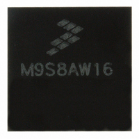
MC9S08AW16MFGE Freescale Semiconductor, MC9S08AW16MFGE Datasheet - Page 179

MC9S08AW16MFGE
Manufacturer Part Number
MC9S08AW16MFGE
Description
IC MCU 8BIT 16K FLASH 44-LQFP
Manufacturer
Freescale Semiconductor
Series
HCS08r
Datasheet
1.MC9S08AW32CFDE.pdf
(324 pages)
Specifications of MC9S08AW16MFGE
Core Processor
HCS08
Core Size
8-Bit
Speed
40MHz
Connectivity
I²C, SCI, SPI
Peripherals
LVD, POR, PWM, WDT
Number Of I /o
34
Program Memory Size
16KB (16K x 8)
Program Memory Type
FLASH
Ram Size
1K x 8
Voltage - Supply (vcc/vdd)
2.7 V ~ 5.5 V
Data Converters
A/D 8x10b
Oscillator Type
Internal
Operating Temperature
-40°C ~ 125°C
Package / Case
44-LQFP
Lead Free Status / RoHS Status
Lead free / RoHS Compliant
Eeprom Size
-
Available stocks
Company
Part Number
Manufacturer
Quantity
Price
Company:
Part Number:
MC9S08AW16MFGE
Manufacturer:
Freescale Semiconductor
Quantity:
10 000
Part Number:
MC9S08AW16MFGE
Manufacturer:
FREESCALE
Quantity:
20 000
- Current page: 179 of 324
- Download datasheet (4Mb)
transferred to the corresponding timer channel registers only after both 8-bit bytes of a 16-bit register have
been written and the timer counter overflows (reverses direction from up-counting to down-counting at the
end of the terminal count in the modulus register). This TPMxCNT overflow requirement only applies to
PWM channels, not output compares.
Optionally, when TPMxCNTH:TPMxCNTL = TPMxMODH:TPMxMODL, the TPM can generate a TOF
interrupt at the end of this count. The user can choose to reload any number of the PWM buffers, and they
will all update simultaneously at the start of a new period.
Writing to TPMxSC cancels any values written to TPMxMODH and/or TPMxMODL and resets the
coherency mechanism for the modulo registers. Writing to TPMxCnSC cancels any values written to the
channel value registers and resets the coherency mechanism for TPMxCnVH:TPMxCnVL.
10.6
The TPM generates an optional interrupt for the main counter overflow and an interrupt for each channel.
The meaning of channel interrupts depends on the mode of operation for each channel. If the channel is
configured for input capture, the interrupt flag is set each time the selected input capture edge is
recognized. If the channel is configured for output compare or PWM modes, the interrupt flag is set each
time the main timer counter matches the value in the 16-bit channel value register. See the
Interrupts, and System Configuration
interrupt mask control bits.
For each interrupt source in the TPM, a flag bit is set on recognition of the interrupt condition such as timer
overflow, channel input capture, or output compare events. This flag may be read (polled) by software to
verify that the action has occurred, or an associated enable bit (TOIE or CHnIE) can be set to enable
hardware interrupt generation. While the interrupt enable bit is set, a static interrupt will be generated
whenever the associated interrupt flag equals 1. It is the responsibility of user software to perform a
sequence of steps to clear the interrupt flag before returning from the interrupt service routine.
10.6.1
TPM interrupt flags are cleared by a 2-step process that includes a read of the flag bit while it is set (1)
followed by a write of 0 to the bit. If a new event is detected between these two steps, the sequence is reset
and the interrupt flag remains set after the second step to avoid the possibility of missing the new event.
10.6.2
The conditions that cause TOF to become set depend on the counting mode (up or up/down). In
up-counting mode, the 16-bit timer counter counts from 0x0000 through 0xFFFF and overflows to 0x0000
on the next counting clock. TOF becomes set at the transition from 0xFFFF to 0x0000. When a modulus
limit is set, TOF becomes set at the transition from the value set in the modulus register to 0x0000. When
the counter is operating in up-/down-counting mode, the TOF flag gets set as the counter changes direction
at the transition from the value set in the modulus register and the next lower count value. This corresponds
to the end of a PWM period. (The 0x0000 count value corresponds to the center of a period.)
Freescale Semiconductor
TPM Interrupts
Clearing Timer Interrupt Flags
Timer Overflow Interrupt Description
chapter for absolute interrupt vector addresses, priority, and local
MC9S08AW60 Data Sheet, Rev 2
Chapter 10 Timer/Pulse-Width Modulator (S08TPMV2)
Resets,
179
Related parts for MC9S08AW16MFGE
Image
Part Number
Description
Manufacturer
Datasheet
Request
R
Part Number:
Description:
Manufacturer:
Freescale Semiconductor, Inc
Datasheet:
Part Number:
Description:
Manufacturer:
Freescale Semiconductor, Inc
Datasheet:
Part Number:
Description:
Manufacturer:
Freescale Semiconductor, Inc
Datasheet:
Part Number:
Description:
Manufacturer:
Freescale Semiconductor, Inc
Datasheet:
Part Number:
Description:
Manufacturer:
Freescale Semiconductor, Inc
Datasheet:
Part Number:
Description:
Manufacturer:
Freescale Semiconductor, Inc
Datasheet:
Part Number:
Description:
Manufacturer:
Freescale Semiconductor, Inc
Datasheet:
Part Number:
Description:
Manufacturer:
Freescale Semiconductor, Inc
Datasheet:
Part Number:
Description:
Manufacturer:
Freescale Semiconductor, Inc
Datasheet:
Part Number:
Description:
Manufacturer:
Freescale Semiconductor, Inc
Datasheet:
Part Number:
Description:
Manufacturer:
Freescale Semiconductor, Inc
Datasheet:
Part Number:
Description:
Manufacturer:
Freescale Semiconductor, Inc
Datasheet:
Part Number:
Description:
Manufacturer:
Freescale Semiconductor, Inc
Datasheet:
Part Number:
Description:
Manufacturer:
Freescale Semiconductor, Inc
Datasheet:
Part Number:
Description:
Manufacturer:
Freescale Semiconductor, Inc
Datasheet:


