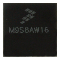
MC9S08AW16MFGE Freescale Semiconductor, MC9S08AW16MFGE Datasheet - Page 65

MC9S08AW16MFGE
Manufacturer Part Number
MC9S08AW16MFGE
Description
IC MCU 8BIT 16K FLASH 44-LQFP
Manufacturer
Freescale Semiconductor
Series
HCS08r
Datasheet
1.MC9S08AW32CFDE.pdf
(324 pages)
Specifications of MC9S08AW16MFGE
Core Processor
HCS08
Core Size
8-Bit
Speed
40MHz
Connectivity
I²C, SCI, SPI
Peripherals
LVD, POR, PWM, WDT
Number Of I /o
34
Program Memory Size
16KB (16K x 8)
Program Memory Type
FLASH
Ram Size
1K x 8
Voltage - Supply (vcc/vdd)
2.7 V ~ 5.5 V
Data Converters
A/D 8x10b
Oscillator Type
Internal
Operating Temperature
-40°C ~ 125°C
Package / Case
44-LQFP
Lead Free Status / RoHS Status
Lead free / RoHS Compliant
Eeprom Size
-
Available stocks
Company
Part Number
Manufacturer
Quantity
Price
Company:
Part Number:
MC9S08AW16MFGE
Manufacturer:
Freescale Semiconductor
Quantity:
10 000
Part Number:
MC9S08AW16MFGE
Manufacturer:
FREESCALE
Quantity:
20 000
- Current page: 65 of 324
- Download datasheet (4Mb)
Chapter 5
Resets, Interrupts, and System Configuration
5.1
This chapter discusses basic reset and interrupt mechanisms and the various sources of reset and interrupts
in the MC9S08AW60 Series. Some interrupt sources from peripheral modules are discussed in greater
detail within other chapters of this data manual. This chapter gathers basic information about all reset and
interrupt sources in one place for easy reference. A few reset and interrupt sources, including the computer
operating properly (COP) watchdog and real-time interrupt (RTI), are not part of on-chip peripheral
systems with their own sections but are part of the system control logic.
5.2
Reset and interrupt features include:
5.3
Resetting the MCU provides a way to start processing from a known set of initial conditions. During reset,
most control and status registers are forced to initial values and the program counter is loaded from the
reset vector ($FFFE:$FFFF). On-chip peripheral modules are disabled and I/O pins are initially configured
as general-purpose high-impedance inputs with pullup devices disabled. The I bit in the condition code
register (CCR) is set to block maskable interrupts so the user program has a chance to initialize the stack
pointer (SP) and system control settings. SP is forced to $00FF at reset.
The MC9S08AW60 Series has seven sources for reset:
Freescale Semiconductor
•
•
•
•
•
•
Multiple sources of reset for flexible system configuration and reliable operation:
— Power-on detection (POR)
— Low voltage detection (LVD) with enable
— External RESET pin
— COP watchdog with enable and two timeout choices
— Illegal opcode
— Serial command from a background debug host
Reset status register (SRS) to indicate source of most recent reset
Separate interrupt vectors for each module (reduces polling overhead) (see
Power-on reset (POR)
Low-voltage detect (LVD)
Computer operating properly (COP) timer
Introduction
Features
MCU Reset
MC9S08AW60 Data Sheet, Rev 2
Table
5-10)
65
Related parts for MC9S08AW16MFGE
Image
Part Number
Description
Manufacturer
Datasheet
Request
R
Part Number:
Description:
Manufacturer:
Freescale Semiconductor, Inc
Datasheet:
Part Number:
Description:
Manufacturer:
Freescale Semiconductor, Inc
Datasheet:
Part Number:
Description:
Manufacturer:
Freescale Semiconductor, Inc
Datasheet:
Part Number:
Description:
Manufacturer:
Freescale Semiconductor, Inc
Datasheet:
Part Number:
Description:
Manufacturer:
Freescale Semiconductor, Inc
Datasheet:
Part Number:
Description:
Manufacturer:
Freescale Semiconductor, Inc
Datasheet:
Part Number:
Description:
Manufacturer:
Freescale Semiconductor, Inc
Datasheet:
Part Number:
Description:
Manufacturer:
Freescale Semiconductor, Inc
Datasheet:
Part Number:
Description:
Manufacturer:
Freescale Semiconductor, Inc
Datasheet:
Part Number:
Description:
Manufacturer:
Freescale Semiconductor, Inc
Datasheet:
Part Number:
Description:
Manufacturer:
Freescale Semiconductor, Inc
Datasheet:
Part Number:
Description:
Manufacturer:
Freescale Semiconductor, Inc
Datasheet:
Part Number:
Description:
Manufacturer:
Freescale Semiconductor, Inc
Datasheet:
Part Number:
Description:
Manufacturer:
Freescale Semiconductor, Inc
Datasheet:
Part Number:
Description:
Manufacturer:
Freescale Semiconductor, Inc
Datasheet:


