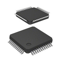
DF71241D50FPV Renesas Electronics America, DF71241D50FPV Datasheet - Page 768

DF71241D50FPV
Manufacturer Part Number
DF71241D50FPV
Description
MCU RISC FLASH 5V 32K 48-LQFP
Manufacturer
Renesas Electronics America
Series
SuperH® SH Tinyr
Datasheet
1.DF71243N50FPV.pdf
(794 pages)
Specifications of DF71241D50FPV
Core Processor
SH-2
Core Size
32-Bit
Speed
50MHz
Connectivity
SCI
Peripherals
POR, PWM, WDT
Number Of I /o
23
Program Memory Size
32KB (32K x 8)
Program Memory Type
FLASH
Ram Size
8K x 8
Voltage - Supply (vcc/vdd)
4 V ~ 5.5 V
Data Converters
A/D 8x10b
Oscillator Type
External
Operating Temperature
-40°C ~ 85°C
Package / Case
48-LQFP
Lead Free Status / RoHS Status
Lead free / RoHS Compliant
Eeprom Size
-
Available stocks
Company
Part Number
Manufacturer
Quantity
Price
Company:
Part Number:
DF71241D50FPV
Manufacturer:
Renesas Electronics America
Quantity:
10 000
- Current page: 768 of 794
- Download datasheet (5Mb)
Rev. 5.00 Mar. 06, 2009 Page 748 of 770
REJ09B0243-0500
Item
1.4 Pin Functions
Table 1.2 Pin Functions
Page Revision (See Manual for Details)
13
14
15
15
Table amended
Table amended
Table amended
Note added
Notes: *1 This pin function is not supported on the 16
Classification
A/D converter
(ADC)
Classification
A/D converter
User debugging
interface
(H-UDI)*
Classification
E10A interface
1
*2 On 32 Kbyte versions (SH71251A,
Kbyte (SH71250A and SH71240A) and 32
Kbyte (SH71251A and SH71241A) versions.
SH71241A) and 16 Kbyte versions
(SH71250A, SH71240A), connect ASEMD0
to V
these versions do not support ASEBRK and
ASEBRKAK.
Symbol
AVcc
Symbol
AVss
TCK
TMS
TDI
TDO
TRST
Symbol
ASEMD0*
ASEBRK*
ASEBRKAK*
CC
via a resistor and fix it high. Note that
2
2
2
I/O
I
I/O
I
I
I
I
O
I
I/O
I
I
O
Name
Name
Analog ground
Test clock
Test mode select Inputs the test-mode select signal.
Test data input
Test data
output
Test reset
Name
ASE mode
Break request
Break mode
acknowledge
Analog power
supply
Power supply pin for the A/D
converter
Connect all AVcc pins to the system
power supply (Vcc) when the A/D
converter is not used.
Function
Function
Ground pin for the A/D converter
Connect it to the system ground (0
V).
Connect all AVss pins to the system
ground (0 V) correctly.
Test-clock input pin
Serial input pin for instructions and
data
Serial output pin for instructions and
data
Initialization-signal input pin
Function
Sets the ASE mode.
When a low-level signal is input to
this pin, the MCU enters ASE mode.
When a high-level signal is input,
MCU enters normal mode (MCU
operation mode or on-chip flash
memory programming mode).
Emulator-specific functions are
available in ASE mode. When no
signal is input, this pin is pulled up
internally.
If only normal mode will be used, pull
up the pin by connecting a resistor.
E10A emulator break input pin
Indicates that the E10A emulator has
entered its break mode.
Related parts for DF71241D50FPV
Image
Part Number
Description
Manufacturer
Datasheet
Request
R

Part Number:
Description:
KIT STARTER FOR M16C/29
Manufacturer:
Renesas Electronics America
Datasheet:

Part Number:
Description:
KIT STARTER FOR R8C/2D
Manufacturer:
Renesas Electronics America
Datasheet:

Part Number:
Description:
R0K33062P STARTER KIT
Manufacturer:
Renesas Electronics America
Datasheet:

Part Number:
Description:
KIT STARTER FOR R8C/23 E8A
Manufacturer:
Renesas Electronics America
Datasheet:

Part Number:
Description:
KIT STARTER FOR R8C/25
Manufacturer:
Renesas Electronics America
Datasheet:

Part Number:
Description:
KIT STARTER H8S2456 SHARPE DSPLY
Manufacturer:
Renesas Electronics America
Datasheet:

Part Number:
Description:
KIT STARTER FOR R8C38C
Manufacturer:
Renesas Electronics America
Datasheet:

Part Number:
Description:
KIT STARTER FOR R8C35C
Manufacturer:
Renesas Electronics America
Datasheet:

Part Number:
Description:
KIT STARTER FOR R8CL3AC+LCD APPS
Manufacturer:
Renesas Electronics America
Datasheet:

Part Number:
Description:
KIT STARTER FOR RX610
Manufacturer:
Renesas Electronics America
Datasheet:

Part Number:
Description:
KIT STARTER FOR R32C/118
Manufacturer:
Renesas Electronics America
Datasheet:

Part Number:
Description:
KIT DEV RSK-R8C/26-29
Manufacturer:
Renesas Electronics America
Datasheet:

Part Number:
Description:
KIT STARTER FOR SH7124
Manufacturer:
Renesas Electronics America
Datasheet:

Part Number:
Description:
KIT STARTER FOR H8SX/1622
Manufacturer:
Renesas Electronics America
Datasheet:

Part Number:
Description:
KIT DEV FOR SH7203
Manufacturer:
Renesas Electronics America
Datasheet:


