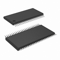
COP8CCE9IMT7/NOPB National Semiconductor, COP8CCE9IMT7/NOPB Datasheet - Page 31

COP8CCE9IMT7/NOPB
Manufacturer Part Number
COP8CCE9IMT7/NOPB
Description
MCU 8BIT FLASH 8K MEM 48-TSSOP
Manufacturer
National Semiconductor
Series
COP8™ 8Cr
Datasheet
1.I2C-CPEV.pdf
(80 pages)
Specifications of COP8CCE9IMT7/NOPB
Core Processor
COP8
Core Size
8-Bit
Speed
10MHz
Connectivity
Microwire/Plus (SPI), UART/USART
Peripherals
Brown-out Detect/Reset, POR, PWM, WDT
Number Of I /o
39
Program Memory Size
8KB (8K x 8)
Program Memory Type
FLASH
Ram Size
256 x 8
Voltage - Supply (vcc/vdd)
2.7 V ~ 5.5 V
Data Converters
A/D 16x10b
Oscillator Type
Internal
Operating Temperature
-40°C ~ 125°C
Package / Case
48-TSSOP
Data Bus Width
8 bit
Maximum Clock Frequency
10 MHz
Data Ram Size
256 B
On-chip Adc
10 bit, 16 channel
Number Of Programmable I/os
37
Number Of Timers
2
Height
0.9 mm
Interface Type
SPI, USART
Length
12.5 mm
Maximum Operating Temperature
+ 125 C
Minimum Operating Temperature
- 40 C
Supply Voltage (max)
5.5 V
Supply Voltage (min)
2.7 V
Width
6.1 mm
Lead Free Status / RoHS Status
Lead free / RoHS Compliant
Eeprom Size
-
Lead Free Status / Rohs Status
Details
Other names
COP8CCE9IMT7
BLOCKR
WRITE_BYTE
BLOCKW
EXIT
INVALID
11.0 In-System Programming
Note: The user must ensure that Block Writes do not cross a 64 byte boundary within one operation.
11.8 USER ISP AND VIRTUAL E
The following commands will support transferring blocks of
data from RAM to flash program memory, and vice-versa.
The user is expected to enforce application security in this
case.
• Erase the entire flash program memory (mass erase).
• Erase a page of flash memory at a specified address.
• Read a byte from a specified address.
• Write a byte to a specified address.
NOTE: Execution of this command will force the device
into the MICROWIRE/PLUS ISP mode.
Command
Block Read
Write Byte
Block Write
EXIT
N/A
Function
TABLE 10. MICROWIRE/PLUS ISP Commands (Continued)
2
(Continued)
Value (Hex)
Command
0xA3
0xD3
0x71
0x8F
31
The following table lists the User ISP/Virtual E
required parameters and return data, if applicable. The com-
mand entry point is used as an argument to the JSRB
instruction. Table 12 lists the Ram locations and Peripheral
Registers, used for User ISP and Virtual E
pected contents. Please refer to the COP8 FLASH ISP User
Manual for additional information and programming ex-
amples on the use of User ISP and Virtual E
• Copy a block of data from RAM into flash program
• Copy a block of data from program flash memory to RAM.
memory.
Address High, Address
Low, Byte Count (n)
High, Byte Count (n)
Low
0 ≤ n ≤ 32767
Address High, Address
Low, Data Byte
Address High, Address
Low, Byte Count (0 ≤ n
≤ 16), n Data Bytes
N/A
Any other invalid
command will be
ignored
Parameters
n Data Bytes if Security
not set.
n Bytes of 0xFF if
Security set.
N/A
N/A
N/A (Device will Reset)
N/A
Return Data
2
, and their ex-
2
.
2
commands,
www.national.com


