FSBB15CH60C Fairchild Semiconductor, FSBB15CH60C Datasheet - Page 17
FSBB15CH60C
Manufacturer Part Number
FSBB15CH60C
Description
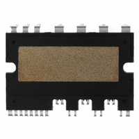
IC POWER MOD SPM 600V SPM27CC
Manufacturer
Fairchild Semiconductor
Series
SPM™r
Type
IGBTr
Specifications of FSBB15CH60C
Configuration
3 Phase
Current
15A
Voltage
600V
Voltage - Isolation
2500Vrms
Package / Case
SPM27CC
Transistor Polarity
N Channel
Dc Collector Current
15A
Collector Emitter Voltage Vces
2V
Power Dissipation Pd
55W
Collector Emitter Voltage V(br)ceo
600V
Operating Temperature Range
-40°C To
Operating Temperature (max)
150C
Operating Temperature (min)
-40C
Pin Count
27
Mounting
Through Hole
Case Length
44mm
Case Height
5.5mm
Screening Level
Automotive
Lead Free Status / RoHS Status
Lead free / RoHS Compliant
Available stocks
Company
Part Number
Manufacturer
Quantity
Price
Company:

Part Number:
FSBB15CH60C
Manufacturer:
CYPRESS
Quantity:
5 610
Part Number:
FSBB15CH60C
Manufacturer:
FSC/ON可看货
Quantity:
20 000


2008-03-03
High-Side Bias Voltage Pins for Driving the IGBT / High-Side Biase Voltage Ground Pins for
Driving the IGBT
Low-Side Bias Voltage Pin / High-Side Bias Voltage Pins
Low-Side Common Supply Ground Pin
Signal Input Pins
Pins : V
Pin : V
Pin : COM
Pin : IN
• These are drive power supply pins for providing gate drive power to the High-Side IGBTs.
• The virtue of the ability to boot-strap the circuit scheme is that no external power supplies are
• Each boot-strap capacitor is charged from the Vcc supply during the ON-state of the
• In order to prevent malfunctions caused by noise and ripple in supply voltage, a good quality (low
• These are control supply pins for the built-in ICs.
• These four pins should be connected externally.
• In order to prevent malfunctions caused by noise and ripple in the supply voltage, a good quality
• The Mini DIP SPM common pin connects to the control ground for the internal ICs.
• Important! To avoid noise influences the main power circuit current should not be allowed to blow
• These are pins to control the operation of the built-in IGBTs .
• They are activated by voltage input signals. The terminals are internally connected to a schmitt
• The signal logic of these pins is Active-high. That is the IGBT associated with each of these
• The wiring of each input should be as short as possible to protect the Mini DIP SPM against
• To prevent signal oscillations, an RC coupling is recommended as illustrated in Fig. 6.1.
required for the high-side IGBTs
corresponding low-side IGBT.
ESR, low ESL) filter capacitor should be mounted very close to these pins
(low ESR, low ESL) filter capacitor should be mounted very close to these pins.
through this pin.
trigger circuit composed of 5V-class CMOS.
pins will be turned "ON" when a sufficient logic voltage is applied to these pins.
noise influences.
CC(L),
(UL)
B(U)
, IN
– V
V
CC(UH),
(VL)
S(U)
, IN
, V
V
(WL)
CC(VH),
B(V)
, IN
– V
V
(UH)
CC(WH)
S(V)
, IN
, V
(VH)
B(W)
, IN
– V
(WH)
S(W)
V4 Mini DIP SPM Application Note (2008-03-03)
17
FAIRCHILD SEMICONDUCTOR - Smart Power Module
Related parts for FSBB15CH60C
Image
Part Number
Description
Manufacturer
Datasheet
Request
R

Part Number:
Description:
Fairchild Semiconductor [IGBT MODULE]
Manufacturer:
Fairchild Semiconductor
Datasheet:

Part Number:
Description:
Discrete Semiconductor Modules
Manufacturer:
Fairchild Semiconductor
Part Number:
Description:
Discrete Semiconductor Modules
Manufacturer:
Fairchild Semiconductor
Part Number:
Description:
This N-Channel MOSFET is produced using Fairchild Semiconductor’s advanced Power Trench® process
Manufacturer:
Fairchild Semiconductor
Datasheet:
Part Number:
Description:
This N-Channel MOSFET is produced using Fairchild Semiconductor’s advanced Power Trench® process
Manufacturer:
Fairchild Semiconductor
Datasheet:
Part Number:
Description:
This N-Channel MOSFET is produced using Fairchild Semiconductor’s advanced PowerTrench® process
Manufacturer:
Fairchild Semiconductor
Datasheet:
Part Number:
Description:
This N-Channel MOSFET is produced using Fairchild Semiconductor’s advanced PowerTrench® process
Manufacturer:
Fairchild Semiconductor
Datasheet:
Part Number:
Description:
This N-Channel MOSFET is produced using Fairchild Semiconductor’s advanced Power Trench® process
Manufacturer:
Fairchild Semiconductor
Datasheet:
Part Number:
Description:
This N-Channel logic Level MOSFETs are produced using Fairchild Semiconductor‘s advanced Power Trench® process that has been special tailored to minimize the on-state resistance and yet maintain superior switching performance
Manufacturer:
Fairchild Semiconductor
Datasheet:
Part Number:
Description:
This N-Channel MOSFET is produced using Fairchild Semiconductor’s advanced Power Trench® process
Manufacturer:
Fairchild Semiconductor
Datasheet:
Part Number:
Description:
This N-Channel SyncFET™ is produced using Fairchild Semiconductor’s advanced PowerTrench® process
Manufacturer:
Fairchild Semiconductor
Datasheet:
Part Number:
Description:
This N-Channel SyncFET™ is produced using Fairchild Semiconductor’s advanced PowerTrench® process
Manufacturer:
Fairchild Semiconductor
Datasheet:
Part Number:
Description:
This N-Channel SyncFET™ is produced using Fairchild Semiconductor’s advanced PowerTrench® process
Manufacturer:
Fairchild Semiconductor
Datasheet:
Part Number:
Description:
This N-Channel logic Level MOSFETs are produced using Fairchild Semiconductor‘s advanced Power Trench® process that has been special tailored to minimize the on-state resistance and yet maintain superior switching performance
Manufacturer:
Fairchild Semiconductor
Datasheet:
Part Number:
Description:
This N-Channel MOSFET is produced using Fairchild Semiconductor’s advanced Power Trench® process that has been especially tailored to minimize the on-state resistance and yet maintain superior switching performance
Manufacturer:
Fairchild Semiconductor
Datasheet: