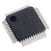
OX16C950-TQBG OXFORD SEMICONDUCTOR, OX16C950-TQBG Datasheet - Page 32

OX16C950-TQBG
Manufacturer Part Number
OX16C950-TQBG
Description
IC, UART, 1CH, SMD, TQFP48, 950
Manufacturer
OXFORD SEMICONDUCTOR
Datasheet
1.OX16C950-TQBG.pdf
(50 pages)
Specifications of OX16C950-TQBG
No. Of Channels
1
Data Rate
15Mbps
Uart Features
Tx/Rx FIFO INT TRIG
Supply Voltage Range
3V To 5.25V
Operating Temperature Range
0°C To +70°C
Digital Ic Case Style
TQFP
No. Of Pins
48
Lead Free Status / RoHS Status
Lead free / RoHS Compliant
Available stocks
Company
Part Number
Manufacturer
Quantity
Price
Company:
Part Number:
OX16C950-TQBG
Manufacturer:
SAMSUNG
Quantity:
450
14.2
The CPR register is located at offset 0x01 of the ICR
The prescaler divides the system clock by any value in the
range of 1 to “31 7/8” in steps of 1/8. The divisor takes the
form “M + N/8”, where M is the 5 bit value defined in
CPR[7:3] and N is the 3 bit value defined in CPR[2:0].
The prescaler is by-passed and a prescaler value of ‘1’ is
selected by default when MCR[7] = 0.
MCR[7] is set to the complement of CLKSEL pin after a
hardware reset but may be overwritten by software. Note
however that since access to MCR[7] is restricted to
Enhanced mode only, EFR[4] should first be set and then
MCR[7] set or cleared as required.
If CLKSEL is connected to ground or MCR[7] is set by
software, the internal clock prescaler is enabled.
Upon a hardware reset, CPR defaults to 0x20 (division-by-
4). Compatibility with existing 16C550 baud rate divisors is
maintained using either a 1.8432MHz clock with CLKSEL
pin connected to VDD, or a 7.372MHz clock with CLKSEL
connected to GND. In the latter case, clearing MCR[7]
would bypass the prescaler and hence quadruple all
selected baud rates (providing a maximum of 460.8kbps as
opposed to 115.2kbps)
For higher baud rates use a higher frequency clock, e.g.
14.7456MHz, 18.432MHz, 32MHz, 40MHz or 60.0MHz.
The flexible prescaler allows system designers to generate
popular baud rates using clocks that are not integer
multiples of the required rate. When using a non-standard
clock frequency, compatibility with existing 16C550
software drivers may be maintained with a minor software
patch to program the on-board prescaler to divide the high
frequency clock down to 1.8432MHz.
Table 17 on the following page gives the prescaler values
required to operate the UARTs at compatible baud rates
with various different crystal frequencies. Also given is the
maximum available baud rates in TCR = 16 and TCR = 4
modes with CPR = 1.
DS-0031 Sep 05
OXFORD SEMICONDUCTOR LTD.
Clock Prescaler Register ‘CPR’
External—Free Release
14.3
The TCR register is located at offset 0x02 of the ICR
The 16C550 and other compatible devices such as 16C650
and 16C750 use a 16 times (16x) over-sampling channel
clock. The 16x over-sampling clock means that the channel
clock runs at 16 times the selected serial bit rate. It limits
the highest baud rate to 1/16 of the system clock when
using a divisor latch value of unity. However, the 16C950
UART is designed in a manner to enable it to accept other
multiplications of the bit rate clock. It can use values from
4x to 16x clock as programmed in the TCR as long as the
clock (oscillator) frequency error, stability and jitter are
within reasonable parameters. Upon hardware reset the
TCR is reset to 0x00 which means that a 16x clock will be
used, for compatibility with the 16C550 and compatibles.
The maximum baud-rates available for various system
clock frequencies at all of the allowable values of TCR are
indicated in Table 18 on the following page. These are the
values in bits-per-second (bps) that are obtained if the
divisor latch = 0x01 and the Prescaler is set to 1.
The OX16C950 has the facility to operate at baud-rates up
to 15 Mbps at 5V.
The table below indicates how the value in the register
corresponds to the number of clock cycles per bit. TCR[3:0]
is used to program the clock. TCR[7:4] are unused and will
return “0000” if read.
The use of TCR does not require the device to be in 650 or
950 mode although only drivers that have been written to
take advantage of the 950 mode features will be able to
access this register. Writing 0x01 to the TCR will not switch
the device into 1x isochronous mode, this is explained in
the following section. (TCR has no effect in isochronous
mode). If 0x01, 0x10 or 0x11 is written to TCR the device
will operate in 16x mode.
Reading TCR will always return the last value that was
written to it irrespective of mode of operation.
Table 16: TCR Sample Clock Configuration
Times Clock Register ‘TCR’
0000 to 0011
0100 to 1111
TCR[3:0]
Clock cycles per bit
OX16C950 rev B
4-15
16
Page 32


