TOOTHPIC RF Solutions, TOOTHPIC Datasheet - Page 49
TOOTHPIC
Manufacturer Part Number
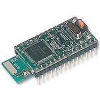
TOOTHPIC
Description
MODULE, BLUETOOTH, DATA ACQUISITION
Manufacturer
RF Solutions
Datasheet
1.TOOTHPIC.pdf
(126 pages)
Specifications of TOOTHPIC
Svhc
No SVHC (15-Dec-2010)


If you have not yet connected the host controller, the red LED may illuminate indicating a serial receive error.
The red LED error indicator is self-resetting and will extinguish after half a second when you have correctly
connected the stamp. You may also get this indication if the host’s baud rate is wrong.
A Quick Tour
To evaluate ToothPIC slave, you are going to be the host. ToothPIC is intended to respond to binary
commands, but it can also accept the same commands if typed in ASCII hexadecimal. To send typed ASCII
hexadecimal commands to ToothPIC Slave, you will need to connect it to a terminal emulator.
instructions which follow assume you will use the HyperTerminal program which comes bundled free with the
Windows operating system. You will need a Windows PC with a serial port (or USB serial port adapter).
Page 49
4. Enter the COM port used to connect to the ToothPIC in the box provided.
5. Press the Update button. Programming takes about 30 seconds. When the progress bar is full, field
6. The serial outputs of ToothPIC are TTL level and need to be converted to RS232 level. For this, we
7. The ToothPIC Slave defaults are deliberately chosen to permit connection to HyperTerminal ‘straight
8. Power up the ToothPIC. After a couple of seconds the LEDs will flash and HyperTerminal should
9. As a first test, we will set an I/O pin as an output and set it high. Connect an LED with a current
programming is complete.
recommend a MAX233 level converter because all voltage doubling components are integrated into
the circuit. Follow the this reference schematic or provide some other circuit:
out of the box’. Once physically connected, start HyperTerminal and select the following settings:
display the following initialization message:
limiting resistor to pin AN11 so that it would light if the pin were high.
9-Apr-06
• Connect using COM port as appropriate.
• 9600 baud (bits per second).
• 8 data bits, no parity, 1 stop bit
• No flow control. (You enable it later after you have enabled Flow Control on the ToothPIC.)
• (In Properties > ASCII Setup) Send line ends with line feeds.
• Echo characters locally.
10536E61766620332E302E3030303032
Vdd
Vss
Toothpick 3.0.00007
1uF
ToothPIC
If you do not have a MAX233, you can use any circuit you wish so long as RxD and TxD are level translated fully duplex.
Slave
Vdd
Vss
When initialized, ToothPIC has no CTS and RTS flow control and you should connect just (i) R2out to T2in.
Circuit is for a DCE configured device for direct connection to DTE device such as a Windows PC.
If you later enable flow control, connect (ii) R2out to CTS and (iii) T2in to RTS as shown instead.
DS380-8
CTS
RTS
RxD
TxD
PIN numbers for MAX233 DIP package. SO package pin numbers differ.
See text below regarding i, ii and iii.
iii
ii
© FlexiPanel Ltd
i
20
20
12
17
1
3
R2out
R1out
16
T2in
T1in
T1in
10
MAX233
Vdd
Patents apply and/or pending
7
T2out
T1out
R2in
R1in
Vss
6 9
19
18
11
15
4
5
DB9 (Female)
connector
Pin 7
Pin 8
Pin 3
Pin 2
Pin 5
9
8
7
6
www.FlexiPanel.com
5
4
3
2
1
The
Related parts for TOOTHPIC
Image
Part Number
Description
Manufacturer
Datasheet
Request
R

Part Number:
Description:
RF Switch SPDT 0MHz to 2GHz 27dB 8-Pin SOIC T/R
Manufacturer:
M/A-Com Technology Solutions
Datasheet:
Part Number:
Description:
RF Switch SPST 500MHz to 2GHz 40dB 8-Pin SOIC T/R
Manufacturer:
M/A-Com Technology Solutions
Datasheet:

Part Number:
Description:
RF Switch SPDT 100MHz to 4GHz 14dB 6-Pin SOT-6
Manufacturer:
Skyworks Solutions Inc
Datasheet:
Part Number:
Description:
RF Switch SPST 500MHz to 2.5GHz 10dB 6-Pin SOT-6
Manufacturer:
Skyworks Solutions Inc

Part Number:
Description:
IC ENCODER TRANSMITTER RF 8DIP
Manufacturer:
RF Solutions
Datasheet:

Part Number:
Description:
IC DECODER RECEIVER RF 18DIP
Manufacturer:
RF Solutions
Datasheet:

Part Number:
Description:
IC ENCODER 3 DGTL I/O SOT23-6
Manufacturer:
RF Solutions
Datasheet:

Part Number:
Description:
IC ENCODER 3 DGTL I/O 8-PDIP
Manufacturer:
RF Solutions
Datasheet:

Part Number:
Description:
IC DECODER 3 DGTL I/O 8-PDIP
Manufacturer:
RF Solutions
Datasheet:

Part Number:
Description:
IC DECODER 3 DGTL I/O 8-SOIC
Manufacturer:
RF Solutions
Datasheet:

Part Number:
Description:
118 SERIES AM REMOTE CONTROL SYSTEMS.
Manufacturer:
RF Solutions Ltd.