TOOTHPIC RF Solutions, TOOTHPIC Datasheet - Page 60
TOOTHPIC
Manufacturer Part Number
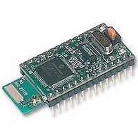
TOOTHPIC
Description
MODULE, BLUETOOTH, DATA ACQUISITION
Manufacturer
RF Solutions
Datasheet
1.TOOTHPIC.pdf
(126 pages)
Specifications of TOOTHPIC
Svhc
No SVHC (15-Dec-2010)


Notes:
I/O pin functions: Pin specifications are ignored for AN inputs if the A to D channels property dictates that
they should be A to D inputs. I/O pin functions must not be sent for pins used for parallel I/O, external
memory and flow control purposes.
Parallel I/O: Pins are modified or read at exactly the same instant.
PWM base time units: Base time units for PWM values. PWM period is in PWM base time units (1 to 256).
PWM duty cycle is in quarter PWM base time units (0 to 1023). PWM time base units turns PWM outputs on
or off, so during initialization, set up period and initial output values first.
Set I/O Command
The command byte 0x03 sets a ToothPIC I/O output value. The byte after the command byte is the Property
Byte, which specifies the exact I/O value being set. The remaining bytes represent the new I/O value, as
follows:
Page 60
9-Apr-06
Configure I/O Command Properties
Property
Byte
0x1C –
0x20
0x21 –
0x22
0x23
0x24
0x25
Configure I/O Command Examples
Set AN0 – AN4 as A to D pins (binary)
Set AN0 – AN4 as A to D pins (ASCII)
Set: PWM time base 3.2µs
Set I/O Command Properties
Property Byte
0x06
0x07
0x10 – 0x1B
0x1C – 0x20
0x21 – 0x22
0x23
0x24
0x25
0x30
0x31
PWM period as 256 (=1220Hz)
CCP2 pin as PWM (binary)
Toothpick 3.0.00007
Property
CCP1 – CCP5 function
INT0 – INT1 function
SCL function
SDA function
SDO function
Property
Parallel I/O A output
Parallel I/O B output
AN0 – AN11 output
CCP1 – CCP5 output
INT0 – INT1 output
SCL output
SDA output
SDO output
Green LED
Red LED
DS380-8
© FlexiPanel Ltd
Remaining Byte(s)
00 = Digital input (default)
01 = Digital output
02 = PWM output
00 = Digital input (default)
01 = Digital output
As INT0
As INT0
As INT0
Remaining Byte(s)
Range 00 to 7F = new value
Range 00 to 1F = new value
00 = low
01 = high
If digital, as AN0 – AN11.
If PWM, range 0000 to 03FF. (Both
As AN0
As AN0
As AN0
As AN0
00 = off
01 = on
00 = off
01 = on
0x04 0x02 0x01 0x05
“04020105<CR><LF>”
0x04 0x02 0x04 0x03
0x04 0x02 0x05 0xFF
0x04 0x02 0x1D 0x02
bytes must be specified.)
Patents apply and/or pending
www.FlexiPanel.com
Related parts for TOOTHPIC
Image
Part Number
Description
Manufacturer
Datasheet
Request
R

Part Number:
Description:
RF Switch SPDT 0MHz to 2GHz 27dB 8-Pin SOIC T/R
Manufacturer:
M/A-Com Technology Solutions
Datasheet:
Part Number:
Description:
RF Switch SPST 500MHz to 2GHz 40dB 8-Pin SOIC T/R
Manufacturer:
M/A-Com Technology Solutions
Datasheet:

Part Number:
Description:
RF Switch SPDT 100MHz to 4GHz 14dB 6-Pin SOT-6
Manufacturer:
Skyworks Solutions Inc
Datasheet:
Part Number:
Description:
RF Switch SPST 500MHz to 2.5GHz 10dB 6-Pin SOT-6
Manufacturer:
Skyworks Solutions Inc

Part Number:
Description:
IC ENCODER TRANSMITTER RF 8DIP
Manufacturer:
RF Solutions
Datasheet:

Part Number:
Description:
IC DECODER RECEIVER RF 18DIP
Manufacturer:
RF Solutions
Datasheet:

Part Number:
Description:
IC ENCODER 3 DGTL I/O SOT23-6
Manufacturer:
RF Solutions
Datasheet:

Part Number:
Description:
IC ENCODER 3 DGTL I/O 8-PDIP
Manufacturer:
RF Solutions
Datasheet:

Part Number:
Description:
IC DECODER 3 DGTL I/O 8-PDIP
Manufacturer:
RF Solutions
Datasheet:

Part Number:
Description:
IC DECODER 3 DGTL I/O 8-SOIC
Manufacturer:
RF Solutions
Datasheet:

Part Number:
Description:
118 SERIES AM REMOTE CONTROL SYSTEMS.
Manufacturer:
RF Solutions Ltd.