TOOTHPIC RF Solutions, TOOTHPIC Datasheet - Page 59
TOOTHPIC
Manufacturer Part Number
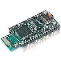
TOOTHPIC
Description
MODULE, BLUETOOTH, DATA ACQUISITION
Manufacturer
RF Solutions
Datasheet
1.TOOTHPIC.pdf
(126 pages)
Specifications of TOOTHPIC
Svhc
No SVHC (15-Dec-2010)


Configure I/O Command
The command byte 0x02 configures the ToothPIC I/O. The byte after the command byte is the Property Byte,
which specifies the exact I/O property being set. The remaining bytes represent the new property value, as
follows:
Page 59
9-Apr-06
Set binary responses (ASCII)
Set cellphone device class (ASCII)
Set time to 13:24:50, April 1st, 2005
(ASCII)
Get time (ASCII)
Configure I/O Command Properties
Property
Byte
0x01
0x02
0x03
0x04
0x05
0x06
0x07
0x10 –
0x1B
Toothpick 3.0.00007
Property
A to D channels
Negative voltage
reference
Positive voltage reference
PWM time base units
PWM period
Parallel I/O A function
Parallel I/O B function
AN0 – AN11 function
(0x10 = AN0, 0x11 =
AN1, etc)
DS380-8
© FlexiPanel Ltd
“04010A00<CR><LF>”
“06010D9FE204<CR><LF>”
“0B014232180D010004D507<CR><LF>”
“030143<CR><LF>”
Remaining Byte(s)
1 byte, range 00 to 0C = Number of analog
to digital channels (from AN0 up).
00 = Vss is –ve voltage reference (default)
01 = AN2 is –ve voltage reference
00 = Vdd is +ve voltage reference (default)
01 = AN3 is +ve voltage reference
00 = Turn PWM off
01 = PWM on, base time unit is 0.2µs
02 = PWM on, base time unit is 0.8µs
03 = PWM on, base time unit is 3.2µs
Range 00 to FF = PWM period in PWM
base time, less one.
00 = Not used
02 = 2-bit output (AN11 – AN10)
03 = 3-bit output (AN11 – AN9)
04 = 4-bit output (AN11 – AN8)
05 = 5-bit output (AN11 – AN7)
06 = 6-bit output (AN11 – AN6)
07 = 7-bit output (AN11 – AN5)
12 = 2-bit input (AN11 – AN10)
13 = 3-bit input (AN11 – AN9)
14 = 4-bit input (AN11 – AN8)
15 = 5-bit input (AN11 – AN7)
16 = 6-bit input (AN11 – AN6)
17 = 7-bit input (AN11 – AN5)
00 = Not used
02 = 2-bit output (AN4 – AN3)
03 = 3-bit output (AN4 – AN2)
04 = 4-bit output (AN4 – AN1)
05 = 5-bit output (AN4 – AN0)
12 = 2-bit input (AN4 – AN3)
13 = 3-bit input (AN4 – AN2)
14 = 4-bit input (AN4 – AN1)
15 = 5-bit input (AN4 – AN0)
00 = Digital input (default)
01 = Digital output
(Ignored if configured for A to D input.)
Patents apply and/or pending
www.FlexiPanel.com
Related parts for TOOTHPIC
Image
Part Number
Description
Manufacturer
Datasheet
Request
R

Part Number:
Description:
RF Switch SPDT 0MHz to 2GHz 27dB 8-Pin SOIC T/R
Manufacturer:
M/A-Com Technology Solutions
Datasheet:
Part Number:
Description:
RF Switch SPST 500MHz to 2GHz 40dB 8-Pin SOIC T/R
Manufacturer:
M/A-Com Technology Solutions
Datasheet:

Part Number:
Description:
RF Switch SPDT 100MHz to 4GHz 14dB 6-Pin SOT-6
Manufacturer:
Skyworks Solutions Inc
Datasheet:
Part Number:
Description:
RF Switch SPST 500MHz to 2.5GHz 10dB 6-Pin SOT-6
Manufacturer:
Skyworks Solutions Inc

Part Number:
Description:
IC ENCODER TRANSMITTER RF 8DIP
Manufacturer:
RF Solutions
Datasheet:

Part Number:
Description:
IC DECODER RECEIVER RF 18DIP
Manufacturer:
RF Solutions
Datasheet:

Part Number:
Description:
IC ENCODER 3 DGTL I/O SOT23-6
Manufacturer:
RF Solutions
Datasheet:

Part Number:
Description:
IC ENCODER 3 DGTL I/O 8-PDIP
Manufacturer:
RF Solutions
Datasheet:

Part Number:
Description:
IC DECODER 3 DGTL I/O 8-PDIP
Manufacturer:
RF Solutions
Datasheet:

Part Number:
Description:
IC DECODER 3 DGTL I/O 8-SOIC
Manufacturer:
RF Solutions
Datasheet:

Part Number:
Description:
118 SERIES AM REMOTE CONTROL SYSTEMS.
Manufacturer:
RF Solutions Ltd.