EVAL-ADAU1761Z Analog Devices Inc, EVAL-ADAU1761Z Datasheet - Page 35
EVAL-ADAU1761Z
Manufacturer Part Number
EVAL-ADAU1761Z
Description
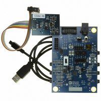
Eval Board For ADAU1761
Manufacturer
Analog Devices Inc
Series
SigmaDSP®r
Specifications of EVAL-ADAU1761Z
Main Purpose
Audio, CODEC
Embedded
Yes, DSP
Utilized Ic / Part
ADAU1761
Primary Attributes
Stereo, 24-Bit, 8 ~ 96 kHz Sampling Rate, GUI Tool
Secondary Attributes
I²C and GPIO Interfaces, 2 Differential and 1 Stereo Single-Ended Analog Inputs and Outputs
Silicon Manufacturer
Analog Devices
Core Architecture
SigmaDSP
Silicon Core Number
ADAU1761
Silicon Family Name
SigmaDSP
Application Sub Type
Audio
Lead Free Status / RoHS Status
Lead free / RoHS Compliant
Available stocks
Company
Part Number
Manufacturer
Quantity
Price
Company:

Part Number:
EVAL-ADAU1761Z
Manufacturer:
Analog Devices Inc
Quantity:
135


PLAYBACK SIGNAL PATH
OUTPUT SIGNAL PATHS
The outputs of the ADAU1761 can be configured as a variety of
differential or single-ended outputs. All analog output pins are
capable of driving headphone or earpiece speakers. There are
selectable output paths for stereo signals or a downmixed mono
output. The line outputs can drive a load of at least 10 kΩ or can
be put into HP mode to drive headphones or earpiece speakers.
The analog output pins are biased at AVDD/2.
With a 0 dBFS digital input and AVDD = 1.8 V, the full-scale
output level is 500 mV rms; when AVDD = 3.3 V, the full-scale
output level is 920 mV rms.
Signals are inverted through the mixers and volume controls.
The result of this inversion is that the polarity of the differential
outputs and the headphone outputs is preserved. The single-
ended mono output is inverted. The DACs are noninverting.
RIGHT INPUT MIXER
RIGHT INPUT MIXER
LEFT INPUT MIXER
LEFT INPUT MIXER
RIGHT DAC
RIGHT DAC
LEFT DAC
LEFT DAC
RAUX
LAUX
MX3AUXG[3:0]
MX4AUXG[3:0]
MX3G1[3:0]
MX3G2[3:0]
MX4G1[3:0]
MX4G2[3:0]
–15dB TO +6dB
–15dB TO +6dB
–15dB TO +6dB
–15dB TO +6dB
–15dB TO +6dB
–15dB TO +6dB
MX3LM
MX3RM
MX4LM
MX4RM
(MONO MIXER)
MX7[1:0]
MIXER 7
Figure 44. Playback Signal Path
PLAYBACK
PLAYBACK
MIXER 3
MIXER 4
(RIGHT
MIXER)
MIXER)
(LEFT
Rev. C | Page 35 of 92
MX6G3[1:0]
MX5G4[1:0]
MX5G3[1:0]
MX6G4[1:0]
Routing Flexibility
The playback path contains five mixers (Mixer 3 to Mixer 7)
that perform the following functions:
•
•
•
Mixer 3 and Mixer 4 are dedicated to mixing signals from the
record path and the DACs. Each of these two mixers can accept
signals from the left and right DACs, the left and right input
mixers, and the dedicated channel auxiliary input. Signals
coming from the record path can be boosted or cut before the
playback mixer.
For example, the MX4G2[3:0] bits set the gain from the output
of Mixer 2 (right record channel) to the input of Mixer 4, hence
the naming convention.
Signals coming from the DACs have digital volume attenu-
ation controls set in Register R20 (left input digital volume
register, Address 0x401A) and Register R21 (right input digital
volume register, Address 0x401B).
Mix signals from the record path and the DACs.
Mix or swap the left and right channels.
Mix a mono signal or generate a common-mode output.
(RIGHT L/R
PLAYBACK
PLAYBACK
(LEFT L/R
MIXER 6
MIXER 5
MIXER)
MIXER)
LHPVOL[5:0]
RHPVOL[5:0]
ROUTVOL[5:0]
LOUTVOL[5:0]
–57dB TO +6dB
–57dB TO +6dB
–1
–1
MONOVOL[5:0]
–57dB TO +6dB
–57dB TO +6dB
–57dB TO +6dB
ADAU1761
LHP
LOUTP
LOUTN
MONOOUT
ROUTN
ROUTP
RHP
Related parts for EVAL-ADAU1761Z
Image
Part Number
Description
Manufacturer
Datasheet
Request
R


Part Number:
Description:
BOARD EVAL FOR SI270X-A
Manufacturer:
Silicon Laboratories Inc
Datasheet:

Part Number:
Description:
BUCK CONV REF DESIGN KIT IP1201
Manufacturer:
International Rectifier
Datasheet:
Part Number:
Description:
BOARD DEMO SYNC DUAL BUCK CNVTER
Manufacturer:
International Rectifier
Datasheet:
Part Number:
Description:
BOARD DEMO SYNC BUCK CONVETER
Manufacturer:
International Rectifier
Datasheet:

Part Number:
Description:
EVALBOARD/EB Omnidirectional microphone - Analog
Manufacturer:
Analog Devices
Datasheet:
Part Number:
Description:
EVALBOARD/EB Omnidirectional microphone - Analog
Manufacturer:
Analog Devices
Datasheet:


Part Number:
Description:
BOARD EVAL LED DRIVER LT3756
Manufacturer:
Linear Technology
Datasheet:

Part Number:
Description:
BOARD EVAL FOR AD7741/7742
Manufacturer:
Analog Devices Inc
Datasheet:

Part Number:
Description:
±1.7g Dual-Axis IMEMS Accelerometer Evaluation Board
Manufacturer:
Analog Devices Inc
Datasheet:

Part Number:
Description:
IC MULTIPLIER ANALOG 8-SOIC T/R
Manufacturer:
Analog Devices Inc
Datasheet:

Part Number:
Description:
IC ANALOG MULTIPLIER 8-DIP
Manufacturer:
Analog Devices Inc
Datasheet:
Part Number:
Description:
IC ANALOG MULTIPLIER 8-SOIC
Manufacturer:
Analog Devices Inc
Datasheet:
Part Number:
Description:
IC ANALOG MULTIPLIER 8-DIP
Manufacturer:
Analog Devices Inc
Datasheet: