KMA199,115 NXP Semiconductors, KMA199,115 Datasheet - Page 17
KMA199,115
Manufacturer Part Number
KMA199,115
Description
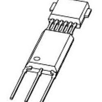
IC SENSOR PROG ANGLE SOT880
Manufacturer
NXP Semiconductors
Datasheet
1.KMA199115.pdf
(36 pages)
Specifications of KMA199,115
Operational Type
Programmable Angle Sensor
Operating Supply Voltage
5 V
Supply Current
5 mA to 10 mA
Package / Case
SOT-880
Mounting Style
Through Hole
Supply Voltage (min)
4.5 V
Supply Voltage (max)
5.5 V
Maximum Output Current
20 mA
Lead Free Status / RoHS Status
Lead free / RoHS Compliant
Available stocks
Company
Part Number
Manufacturer
Quantity
Price

Part Number:
KMA199,115
Manufacturer:
NXP/恩智浦
Quantity:
20 000


NXP Semiconductors
KMA199_1
Product data sheet
13.2 Timing characteristics
During communication, the KMA199 is always the slave and the external programming
hardware is the master.
The master provides the start condition, which is a rising edge after a LOW level. Then a
command byte which can be either a read or a write command is send. Depending on the
command, the master or the slave has to send the data immediately after the command
sequence. In the case of a read command, an additional handover or takeover bit is
inserted before and after the data bytes. Each communication must be closed with a stop
condition driven by the master. If the slave does not receive a rising edge for a time longer
than t
condition and a new command. This can be used to synchronize the device regardless of
the previous state.
All communication is based on this structure (see
command mode. In this case a special write command is required, followed by the
command sequence (two data bytes). The customer can access the EEPROM, CTRL1,
TESTCTRL0 and SIGNATURE registers (described in
reset will leave the command mode. A more detailed description of the programming is
given in the next sections.
As described in the previous section, a start and stop condition is necessary for
communication. The LOW-level duration before the rising edge of the start condition is
defined as t
defined as t
shown in
Fig 12. OWI data format
Fig 13. OWI start and stop condition
to
, a time-out condition occurs. The bus is reset to the idle state and waits for a start
IDLE
IDLE START COMMAND HANDOVER
write
read
Table
start
stop
START
. The HIGH-level duration after the rising edge of the stop condition is
. These parameters, together with all other timing characteristics are
13.
All information provided in this document is subject to legal disclaimers.
COMMAND DATA BYTE 1 DATA BYTE 2
Rev. 01 — 26 April 2010
Figure 12
t
start
illustrates the structure of the OWI data format.
DATA BYTE 1 DATA BYTE 2
Figure
STOP
t
stop
Section
12), even for entering the
Programmable angle sensor
001aag817
TAKEOVER STOP IDLE
13.5). Only a power-on
IDLE
© NXP B.V. 2010. All rights reserved.
KMA199
001aag742
17 of 36
Related parts for KMA199,115
Image
Part Number
Description
Manufacturer
Datasheet
Request
R

Part Number:
Description:
NXP Semiconductors designed the LPC2420/2460 microcontroller around a 16-bit/32-bitARM7TDMI-S CPU core with real-time debug interfaces that include both JTAG andembedded trace
Manufacturer:
NXP Semiconductors
Datasheet:

Part Number:
Description:
NXP Semiconductors designed the LPC2458 microcontroller around a 16-bit/32-bitARM7TDMI-S CPU core with real-time debug interfaces that include both JTAG andembedded trace
Manufacturer:
NXP Semiconductors
Datasheet:
Part Number:
Description:
NXP Semiconductors designed the LPC2468 microcontroller around a 16-bit/32-bitARM7TDMI-S CPU core with real-time debug interfaces that include both JTAG andembedded trace
Manufacturer:
NXP Semiconductors
Datasheet:
Part Number:
Description:
NXP Semiconductors designed the LPC2470 microcontroller, powered by theARM7TDMI-S core, to be a highly integrated microcontroller for a wide range ofapplications that require advanced communications and high quality graphic displays
Manufacturer:
NXP Semiconductors
Datasheet:
Part Number:
Description:
NXP Semiconductors designed the LPC2478 microcontroller, powered by theARM7TDMI-S core, to be a highly integrated microcontroller for a wide range ofapplications that require advanced communications and high quality graphic displays
Manufacturer:
NXP Semiconductors
Datasheet:
Part Number:
Description:
The Philips Semiconductors XA (eXtended Architecture) family of 16-bit single-chip microcontrollers is powerful enough to easily handle the requirements of high performance embedded applications, yet inexpensive enough to compete in the market for hi
Manufacturer:
NXP Semiconductors
Datasheet:
Part Number:
Description:
The XA-S3 device is a member of Philips Semiconductors? XA(eXtended Architecture) family of high performance 16-bitsingle-chip microcontrollers
Manufacturer:
NXP Semiconductors
Datasheet:

Part Number:
Description:
The NXP BlueStreak LH75401/LH75411 family consists of two low-cost 16/32-bit System-on-Chip (SoC) devices
Manufacturer:
NXP Semiconductors
Datasheet:
Part Number:
Description:
The NXP LPC3130/3131 combine an 180 MHz ARM926EJ-S CPU core, high-speed USB2
Manufacturer:
NXP Semiconductors
Datasheet:
Part Number:
Description:
The NXP LPC3141 combine a 270 MHz ARM926EJ-S CPU core, High-speed USB 2
Manufacturer:
NXP Semiconductors
Part Number:
Description:
The NXP LPC3143 combine a 270 MHz ARM926EJ-S CPU core, High-speed USB 2
Manufacturer:
NXP Semiconductors

Part Number:
Description:
The NXP LPC3152 combines an 180 MHz ARM926EJ-S CPU core, High-speed USB 2
Manufacturer:
NXP Semiconductors
Part Number:
Description:
The NXP LPC3154 combines an 180 MHz ARM926EJ-S CPU core, High-speed USB 2
Manufacturer:
NXP Semiconductors

Part Number:
Description:
Standard level N-channel enhancement mode Field-Effect Transistor (FET) in a plastic package using NXP High-Performance Automotive (HPA) TrenchMOS technology
Manufacturer:
NXP Semiconductors
Datasheet: