FGH75N60UFTU Fairchild Semiconductor, FGH75N60UFTU Datasheet

IGBT N-CH 600V 75A TO-247

FGH75N60UFTU

Manufacturer Part Number
FGH75N60UFTU
Description
IGBT N-CH 600V 75A TO-247
Manufacturer
Fairchild Semiconductor
Datasheet

Specifications of FGH75N60UFTU

Igbt Type
Field Stop
Voltage - Collector Emitter Breakdown (max)
600V
Vce(on) (max) @ Vge, Ic
2.4V @ 15V, 75A
Current - Collector (ic) (max)
150A
Power - Max
452W
Input Type
Standard
Mounting Type
Through Hole
Package / Case
TO-247-3
Channel Type
N
Configuration
Single
Collector-emitter Voltage
600V
Gate To Emitter Voltage (max)
±20V
Pin Count
3 +Tab
Mounting
Through Hole
Operating Temperature (max)
150C
Operating Temperature Classification
Military
Collector- Emitter Voltage Vceo Max
600 V
Maximum Gate Emitter Voltage
+/- 20 V
Maximum Operating Temperature
+ 150 C
Continuous Collector Current Ic Max
150 A
Minimum Operating Temperature
- 55 C
Mounting Style
Through Hole
Lead Free Status / RoHS Status
Lead free / RoHS Compliant

Available stocks

Company
Part Number
Manufacturer
Quantity
Price
Part Number:
FGH75N60UFTU
Manufacturer:
FAIRCHILD
Quantity:
2 400
©2009 Fairchild Semiconductor Corporation
FGH75N60UF Rev. A1
Absolute Maximum Ratings
Notes:
1: Repetitive rating: Pulse width limited by max. junction temperature
Thermal Characteristics
FGH75N60UF
600V, 75A Field Stop IGBT
Features
• High Current Capability
• Low Saturation Voltage: V
• High Input Impedance
• Fast Switching
• RoHS Compliant
Applications
• Induction Heating, UPS, SMPS, PFC
V
V
I
I
P
T
T
T
R
R
C
CM (1)
stg
J
L
CES
GES
D
JC
JA
Symbol
Symbol
(IGBT)
Collector to Emitter Voltage
Gate to Emitter Voltage
Collector Current
Collector Current
Pulsed Collector Current
Maximum Power Dissipation
Operating Junction Temperature
Storage Temperature Range
Maximum Lead Temp. for soldering
Purposes, 1/8” from case for 5 seconds
Thermal Resistance, Junction to Case
Thermal Resistance, Junction to Ambient
CE(sat)
=1.9V @ I
E
COLLECTOR
C
(FLANGE)
Description
Parameter
G
C
= 75A
@ T
@ T
@ T
@ T
@ T
C
C
C
C
C
1
= 25
= 100
= 25
= 25
= 100
General Description
Using Novel Field Stop IGBT Technology, Fairchild’s new
series of Field Stop IGBTs offer the optimum performance for
Induction Heating, UPS, SMPS and PFC applications where low
conduction and switching losses are essential.
o
o
o
C
C
C
o
o
C
C
Typ.
-
-
-55 to +150
-55 to +150
Ratings
 20
600
150
225
452
181
300
75
Max.
0.276
40
April 2009
www.fairchildsemi.com
Units
Units
o
o
C/W
C/W
o
o
o
W
W
V
V
A
A
A
C
C
C
tm

Related parts for FGH75N60UFTU

FGH75N60UFTU Summary of contents

Page 1

... R (IGBT) Thermal Resistance, Junction to Case JC R Thermal Resistance, Junction to Ambient JA ©2009 Fairchild Semiconductor Corporation FGH75N60UF Rev. A1 General Description Using Novel Field Stop IGBT Technology, Fairchild’s new series of Field Stop IGBTs offer the optimum performance for = 75A C Induction Heating, UPS, SMPS and PFC applications where low conduction and switching losses are essential ...

Page 2

... Package Marking and Ordering Information Device Marking Device FGH75N60UF FGH75N60UFTU Electrical Characteristics of the IGBT Symbol Parameter Off Characteristics BV Collector to Emitter Breakdown Voltage V CES BV Temperature Coefficient of Breakdown CES T Voltage J I Collector Cut-Off Current CES I G-E Leakage Current GES On Characteristics V G-E Threshold Voltage ...

Page 3

Typical Performance Characteristics Figure 1. Typical Output Characteristics 225 20V 180 135 Collector-Emitter Voltage, V Figure 3. Typical Saturation Voltage Characteristics 225 Common Emitter V = 15V ...

Page 4

Typical Performance Characteristics Figure 7. Saturation Voltage vs 75A I = 40A Gate-Emitter Voltage, V Figure 9. Capacitance Characteristics 8000 6000 C ies 4000 C oes 2000 C res ...

Page 5

Typical Performance Characteristics Figure 13. Turn-on Characteristics vs. Gate Resistance 200 100 t r Common Emitter t d(on Gate Resistance, R Figure 15. Turn-on Characteristics vs. Collector Current 1000 Common Emitter  ...

Page 6

Typical Performance Characteristics Figure 19. Turn off Switching SOA Characteristics 500 100 10 Safe Operating Area 15V 125 Collector-Emitter Voltage, V Figure 20. Transient Thermal Impedance of IGBT 1 ...

Page 7

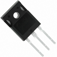
Mechanical Dimensions TO-247AB (FKS PKG CODE 001) FGH75N60UF Rev Dimensions in Millimeters www.fairchildsemi.com ...

Page 8

... TRADEMARKS The following includes registered and unregistered trademarks and service marks, owned by Fairchild Semiconductor and/ global subsi d iaries, and is not intended exhaustive list of all such trademarks. Auto-SPM F-PFS FRFET Build it Now CorePLUS Global Power Resource CorePOWER ...

Related keywords