IKW08T120 Infineon Technologies, IKW08T120 Datasheet - Page 4
IKW08T120
Manufacturer Part Number
IKW08T120
Description
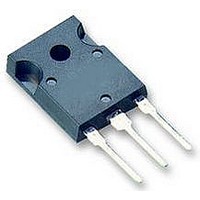
IGBT 1200V 16A 70W TO247-3
Manufacturer
Infineon Technologies
Series
TrenchStop™r
Datasheet
1.IKW08T120.pdf
(16 pages)
Specifications of IKW08T120
Igbt Type
NPT, Trench and Field Stop
Voltage - Collector Emitter Breakdown (max)
1200V
Vce(on) (max) @ Vge, Ic
2.2V @ 15V, 8A
Current - Collector (ic) (max)
16A
Power - Max
70W
Input Type
Standard
Mounting Type
Through Hole
Package / Case
TO-247-3 (Straight Leads)
Transistor Type
IGBT
Dc Collector Current
16A
Collector Emitter Voltage Vces
2.2V
Power Dissipation Max
70W
Collector Emitter Voltage V(br)ceo
1.2kV
Operating Temperature Range
-40°C To +150°C
Power Dissipation Pd
70W
Rohs Compliant
Yes
Switching Frequency
TRENCHSTOP 2-20kHz
Package
TO-247
Vce (max)
1,200.0 V
Ic(max) @ 25°
16.0 A
Ic(max) @ 100°
8.0 A
Lead Free Status / RoHS Status
Lead free / RoHS Compliant
Available stocks
Company
Part Number
Manufacturer
Quantity
Price
Company:

Part Number:
IKW08T120
Manufacturer:
NEC
Quantity:
30 000
Part Number:
IKW08T120
Manufacturer:
INFINEON/英飞凌
Quantity:
20 000
Part Number:
IKW08T120 K08T120
Manufacturer:
INFINEON/英飞凌
Quantity:
20 000


Dynamic Characteristic
Input capacitance
Output capacitance
Reverse transfer capacitance
Gate charge
Internal emitter inductance
measured 5mm (0.197 in.) from case
Short circuit collector current
Switching Characteristic, Inductive Load, at T
Parameter
IGBT Characteristic
Turn-on delay time
Rise time
Turn-off delay time
Fall time
Turn-on energy
Turn-off energy
Total switching energy
Anti-Parallel Diode Characteristic
Diode reverse recovery time
Diode reverse recovery charge
Diode peak reverse recovery current
Diode peak rate of fall of reverse
recovery current during t
1)
2)
Power Semiconductors
Allowed number of short circuits: <1000; time between short circuits: >1s.
Leakage inductance L a nd Stray capacity C due to dynamic test circuit in Figure E.
b
1)
C
C
C
Q
L
I
t
t
t
t
E
E
E
t
Q
I
d i
Symbol
C ( S C )
d ( o n )
r
d ( o f f )
f
r r
r r m
E
o n
o f f
t s
i s s
o s s
r s s
G a t e
r r
r r
/d t
TrenchStop
j
=25 C
4
V
V
f= 1 MH z
V
V
V
V
T
T
V
V
R
L
C
Energy losses include
“tail” and diode
reverse recovery.
T
V
d i
j
j
j
C E
G E
C C
G E
G E
C C
C C
G E
R
G
=2 5 C ,
=2 5 C ,
F
2 )
= 25 C
2 )
= 6 00 V , I
= 81 ,
/ d t =6 0 0 A/ s
= 25 V ,
= 0V ,
= 96 0 V, I
= 15 V
= 15 V ,t
= 60 0 V, I
= 0/ 15 V ,
=1 8 0n H,
= 3 9p F
= 6 0 0 V,
Conditions
®
Series
S C
F
C
= 8 A,
C
= 8 A,
=8 A
10 s
min.
-
-
-
-
-
-
-
-
-
-
-
-
-
-
-
-
-
IKW08T120
Value
0.67
1.37
typ.
600
450
420
0.7
1.0
36
28
53
13
48
40
23
70
80
13
Rev. 2.2 Dec 07
max.
-
-
-
-
-
-
-
-
-
-
-
-
-
-
-
-
-
pF
nC
nH
A
Unit
ns
mJ
ns
µC
A
A/ s
Related parts for IKW08T120
Image
Part Number
Description
Manufacturer
Datasheet
Request
R

Part Number:
Description:
Manufacturer:
Infineon Technologies AG
Datasheet:
Part Number:
Description:
Manufacturer:
Infineon Technologies AG
Datasheet:
Part Number:
Description:
Manufacturer:
Infineon Technologies AG
Datasheet:
Part Number:
Description:
Manufacturer:
Infineon Technologies AG
Datasheet:
Part Number:
Description:
Manufacturer:
Infineon Technologies AG
Datasheet:
Part Number:
Description:
Manufacturer:
Infineon Technologies AG
Datasheet:
Part Number:
Description:
Manufacturer:
Infineon Technologies AG
Datasheet:
Part Number:
Description:
16-bit microcontroller with 2x2 KByte RAM
Manufacturer:
Infineon Technologies AG
Datasheet:
Part Number:
Description:
NPN silicon RF transistor
Manufacturer:
Infineon Technologies AG
Datasheet:
Part Number:
Description:
NPN silicon RF transistor
Manufacturer:
Infineon Technologies AG
Datasheet:
Part Number:
Description:
NPN silicon RF transistor
Manufacturer:
Infineon Technologies AG
Datasheet:
Part Number:
Description:
NPN silicon RF transistor
Manufacturer:
Infineon Technologies AG
Datasheet:
Part Number:
Description:
Si-MMIC-amplifier in SIEGET 25-technologie
Manufacturer:
Infineon Technologies AG
Datasheet:
Part Number:
Description:
IGBT Power Module
Manufacturer:
Infineon Technologies AG
Datasheet:
Part Number:
Description:
IC for switching-mode power supplies
Manufacturer:
Infineon Technologies AG
Datasheet: