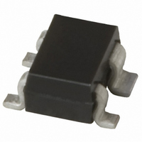
BGB 540 E6327 Infineon Technologies, BGB 540 E6327 Datasheet

BGB 540 E6327
Specifications of BGB 540 E6327
SP000013194
Related parts for BGB 540 E6327
BGB 540 E6327 Summary of contents
Page 1
BGB 420 MMIC ...
Page 2
... Infineon Technologies Office. Infineon Technologies Components may only be used in life-support devices or systems with the express written approval of Infineon Technologies failure of such components can reasonably be expected to cause the failure of that life-support device or system affect the safety or effectiveness of that device or system. Life support devices or systems are intended to be implanted in the human body support and/or maintain and sustain and/or protect human life ...
Page 3
... Subjects (major changes since last revision) 7 S-Parameter table added 8 Figure “Output Compression Point” added 9 SPICE Model added For questions on technology, delivery and prices please contact the Infineon Technologies Offices in Germany or the Infineon Technologies Companies and Representatives worldwide: see our webpage at http://www.infineon.com 2001-08-10 2000-11-28 ...
Page 4
BGB420 Active Biased Transistor Features • For high gain low noise amplifiers • Ideal for wideband applications, cellular telephones, cordless telephones, SAT-TV and high frequency oscillators • G =17.5dB at 1.8GHz ma • Small SOT343 package • Current easy adjustable ...
Page 5
Maximum Ratings Parameter Maximum collector-emitter voltage Maximum collector current Maximum bias current Maximum emitter-base voltage Maximum base current Total power dissipation, T Junction temperature Operating temperature range Storage temperature range Thermal resistance: junction-soldering point Notes: For detailed symbol description refer ...
Page 6
RF In Fig. 2: Test Circuit for Electrical Characteristics and S-Parameter Electrical Characteristics at T min./max. values verified by random sampling) Parameter Maximum available power gain V =2V, I =20mA, f=1.8GHz D c Insertion power gain =2V, I =20mA V ...
Page 7
S-Parameter V =2V, I =20mA (see Electrical Characteristics for conditions Frequency S11 S11 [GHz] Mag Ang 0.1 0.4412 -24.8 0.2 0.4064 -47.4 0.4 0.3261 -81.6 0.6 0.2854 -105.8 0.8 0.2615 -124.2 1.0 0.2525 -136.4 1.2 0.2505 -148.9 1.4 ...
Page 8
Power Gain | Gma, Gms=f( 3V, I =20mA Gma/Gms Frequency [GHz] Matching |S |,|S |=f( ...
Page 9
SPICE Model BGB420-Chip Transistor Chip Data T502 (Berkley-SPICE 2G.6 Syntax) .MODEL T502 NPN 2.0045e- 72.534 + IKF = 0.48731 ISE = 1.9049e- 1.3325 VAR = 19.705 + ...
Page 10
Typical Application DC Bypass V Bias R Bias I Bias 4 BGB420 Package Outline 2 ±0.2 1.3 ±0 +0.1 0.3 Data sheet Fig. 3: Typical application circuit. Voltage Supply This how to use the ...


