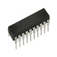
ML4819CP_NL Fairchild Semiconductor, ML4819CP_NL Datasheet - Page 10

ML4819CP_NL
Manufacturer Part Number
ML4819CP_NL
Description
Manufacturer
Fairchild Semiconductor
Datasheet
1.ML4819CP_NL.pdf
(15 pages)
Specifications of ML4819CP_NL
Start-up Supply Current
600uA
Operating Supply Voltage (max)
35V
Operating Temp Range
0C to 70C
Operating Temperature Classification
Commercial
Package Type
PDIP
Pin Count
20
Mounting
Through Hole
Lead Free Status / RoHS Status
Compliant
ML4819
then:
Step 3: The value of the inductance can now be found
The inductor can be allowed to decrease in value when
the current sweeps from minimum to maximum value.
This allows the use of smaller core sizes. The only
requirement is that the ramp compensation must be
adequate for the lower inductance value of the core so
that there is adequate compensation at high current.
Step 4: The presence of the ramp compensation will
Gapped Ferrites, Molypermalloy, and Powdered Iron cores
are typical choices for core material. The core material
selected should have a high saturation point and
acceptable losses at the operating frequency.
One ferrite core that is suitable at around 200W is the
#4229PL00-3C8 made by Ferroxcube. This ungapped core
will require a total gap of 0.180" for this application.
OSCILLATOR COMPONENT SELECTION
The oscillator timing components can be calculated by
using the following expression:
For example:
Step 1: At 100kHz with 95% duty cycle T
Step 2: Calculate the required value of the timing
resistor.
10
L
R
f
C
OSC
1
T
T
I
using previously calculated data.
change the dry out point, but the value found
above can be considered a good starting point.
Based on the amount of power factor correction
the value of L1 can be optimized after a few
iterations.
calculate C
100
LDRY
V
13 6
INDRY
f
t
OSC
OFF
R
20
.
I
mA
L DRY
1 36
V
T
(
1 36
k
.
OSC
= 100mA
V
.
.
C
I
C
DIS
)
Choose R
D
100
T
0 95
T
.
ON MAX
T
f
OSC
using the following formula:
kHz
100
1000
(
kHz
T
)
pF
2
1 36
mH
.
14
1000
k
.
pF
OFF
= 500ns
(5)
(6)
(7)
(8)
CURRENT SENSE AND SLOPE (RAMP) COMPENSATION
COMPONENT SELECTION
Slope compensation in the ML4819 is provided internally.
A current equal to V
this is converted to a voltage by R10, adding slope to the
sensed current through T1. The amount of slope
compensation should be at least 50% of the downslope of
the inductor current during the off time as reflected on pin
1. Note that slope compensation is a requirement only if
the inductor current is continuous and the duty cycle is
more than 50%. The highest inductor downslope is found
at the point of inductor discontinuity:
The downslope as reflected to the input of the PWM
comparator is given by:
Where N
used. In general, current transformers simplify the sensing of
switch currents, especially at high power levels where the
use of sense resistors is complicated by the amount of
power they have to dissipate. Normally the primary side
of the transformer consists of a single turn and the
secondary consists of several turns of either enameled
magnet wire or insulated wire. The diameter of the ferrite
core used in this example is 0.5" (SPANG/Magnetics
F41206-TC). The rectifying diode at the output of the
current transformer can be a 1N4148 for secondary
currents up to 75mA average.
Current-sensing MOSFETs or resistive sensing can also be
used to sense the switch current. In these cases, the
sensed signal has to be amplified to the proper level
before it is applied to the ML4819.
The value of the ramp compensation (SC
pin 1 is:
The required value for R
equating:
where A
solving for R
SC
SC
di
S
dt
PWM
L
PWM
PWM
SC
C
V
is the turns ratio of the current transformer (T1)
is the amount of slope compensation and
B
18
V
A
B
R
.
V
L
16
SC
IN DRY
2 5
V
L
.
IN DRY
1
C
S
CT
PWM
6
R
/2(R18) is added to I
9
18
R
380
18
can therefore be found by
R
N
2
11
V
C
mH
20
V
REV. 1.0 10/10/2000
0 18
.
PWM
SENSE
A
) as seen at
/
s
A (pin 1).
(10)
(11)
(9)


