EZ80F920120MOD Zilog, EZ80F920120MOD Datasheet - Page 121
EZ80F920120MOD
Manufacturer Part Number
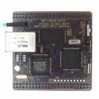
EZ80F920120MOD
Description
MODULE EZ80F92 512K 20MHZ
Manufacturer
Zilog
Datasheets
1.EZ80F920120MOD.pdf
(269 pages)
2.EZ80F920120MOD.pdf
(4 pages)
3.EZ80F920120MOD.pdf
(2 pages)
Specifications of EZ80F920120MOD
Module/board Type
Development Module
Processor Series
EZ80F92x
Core
eZ80
Data Bus Width
8 bit
Program Memory Type
Flash
Program Memory Size
1 MB
Interface Type
Cable
Maximum Clock Frequency
20 MHz
Operating Supply Voltage
0 V to 3.3 V
Maximum Operating Temperature
+ 70 C
Mounting Style
SMD/SMT
Package / Case
LQFP
Development Tools By Supplier
eZ80F920200ZCOG
Minimum Operating Temperature
0 C
For Use With/related Products
eZ80F92
Lead Free Status / RoHS Status
Contains lead / RoHS non-compliant
Other names
269-3157
EZ80F920120MOD
EZ80F920120MOD


PS015308-0404
UART Transmitter Interrupt
The transmitter hold register empty interrupt is generated if there is no data available in
the hold register. The transmission complete interrupt is generated after the data in the
shift register is sent. Both interrupts can be disabled using individual interrupt enable bits
or cleared by writing data into the UARTx_THR register.
UART Receiver Interrupts
A receiver interrupt can be generated by three possible sources. The first source, a
Receiver Data Ready, indicates that one or more data bytes are received and are ready to
be read. This interrupt is generated if the number of bytes in the receiver FIFO is greater
than or equal to the trigger level. If the FIFO is not enabled, the interrupt is generated if the
receive buffer contains a data byte. This interrupt is cleared by reading the UARTx_RBR.
The second interrupt source is the receiver time-out. A receiver time-out interrupt is gener-
ated when there are fewer data bytes in the receiver FIFO than the trigger level and there
are no reads and writes to or from the receiver FIFO for four consecutive byte times. When
the receiver time-out interrupt is generated, it is cleared only after emptying the entire
receive FIFO.
The first two interrupt sources from the receiver (data ready and time-out) share an inter-
rupt enable bit.
The third source of a receiver interrupt is a line status error, indicating an error in byte
reception. This error may result from:
•
•
•
•
An interrupt due to one of the above conditions is cleared when the UARTx_LSR register
is read. In FIFO mode, a line status interrupt is generated only after the received byte with
an error reaches the top of the FIFO and is ready to be read.
A line status interrupt is activated (provided this interrupt is enabled) as long as the Read
pointer of the receiver FIFO points to the location of the FIFO that contains a byte with the
error. The interrupt is immediately cleared when the UARTx_LSR register is read. The
ERR bit of the UARTx_LSR register is active as long as an erroneous byte is present in the
receiver FIFO.
UART Modem Status Interrupt
The modem status interrupt is generated if there is any change in state of the modem status
inputs to the UART. This interrupt is cleared when the processor reads the UARTx_MSR
register.
Incorrect received parity. For 9-bit data, incorrect parity indicates detection of an
address byte
Incorrect framing; that is, the stop bit is not detected by receiver at the end of the byte
Receiver over run condition
A BREAK condition being detected on the receive data input
P R E L I M I N A R Y
Universal Asynchronous Receiver/Transmitter
Product Specification
eZ80F92/eZ80F93
109
Related parts for EZ80F920120MOD
Image
Part Number
Description
Manufacturer
Datasheet
Request
R

Part Number:
Description:
Communication Controllers, ZILOG INTELLIGENT PERIPHERAL CONTROLLER (ZIP)
Manufacturer:
Zilog, Inc.
Datasheet:

Part Number:
Description:
KIT DEV FOR Z8 ENCORE 16K TO 64K
Manufacturer:
Zilog
Datasheet:

Part Number:
Description:
KIT DEV Z8 ENCORE XP 28-PIN
Manufacturer:
Zilog
Datasheet:

Part Number:
Description:
DEV KIT FOR Z8 ENCORE 8K/4K
Manufacturer:
Zilog
Datasheet:

Part Number:
Description:
KIT DEV Z8 ENCORE XP 28-PIN
Manufacturer:
Zilog
Datasheet:

Part Number:
Description:
DEV KIT FOR Z8 ENCORE 4K TO 8K
Manufacturer:
Zilog
Datasheet:
Part Number:
Description:
CMOS Z8 microcontroller. ROM 16 Kbytes, RAM 256 bytes, speed 16 MHz, 32 lines I/O, 3.0V to 5.5V
Manufacturer:
Zilog, Inc.
Datasheet:
Part Number:
Description:
Low-cost microcontroller. 512 bytes ROM, 61 bytes RAM, 8 MHz
Manufacturer:
Zilog, Inc.
Datasheet:
Part Number:
Description:
Z8 4K OTP Microcontroller
Manufacturer:
Zilog, Inc.
Datasheet:
Part Number:
Description:
CMOS SUPER8 ROMLESS MCU
Manufacturer:
Zilog, Inc.
Datasheet:
Part Number:
Description:
SL1866 CMOSZ8 OTP Microcontroller
Manufacturer:
Zilog, Inc.
Datasheet:
Part Number:
Description:
SL1866 CMOSZ8 OTP Microcontroller
Manufacturer:
Zilog, Inc.
Datasheet:
Part Number:
Description:
OTP (KB) = 1, RAM = 125, Speed = 12, I/O = 14, 8-bit Timers = 2, Comm Interfaces Other Features = Por, LV Protect, Voltage = 4.5-5.5V
Manufacturer:
Zilog, Inc.
Datasheet:
Part Number:
Description:
Manufacturer:
Zilog, Inc.
Datasheet: