EZ80F920120MOD Zilog, EZ80F920120MOD Datasheet - Page 266
EZ80F920120MOD
Manufacturer Part Number
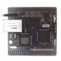
EZ80F920120MOD
Description
MODULE EZ80F92 512K 20MHZ
Manufacturer
Zilog
Datasheets
1.EZ80F920120MOD.pdf
(269 pages)
2.EZ80F920120MOD.pdf
(4 pages)
3.EZ80F920120MOD.pdf
(2 pages)
Specifications of EZ80F920120MOD
Module/board Type
Development Module
Processor Series
EZ80F92x
Core
eZ80
Data Bus Width
8 bit
Program Memory Type
Flash
Program Memory Size
1 MB
Interface Type
Cable
Maximum Clock Frequency
20 MHz
Operating Supply Voltage
0 V to 3.3 V
Maximum Operating Temperature
+ 70 C
Mounting Style
SMD/SMT
Package / Case
LQFP
Development Tools By Supplier
eZ80F920200ZCOG
Minimum Operating Temperature
0 C
For Use With/related Products
eZ80F92
Lead Free Status / RoHS Status
Contains lead / RoHS non-compliant
Other names
269-3157
EZ80F920120MOD
EZ80F920120MOD


Setting Timer Duration 79
Shift Left Arithmetic 149, 151, 155, 215
Shift Right Arithmetic 215
SINGLE PASS mode 78–79, 80–81, 84
Single-Byte I/O Write Operations 198
SLA—see Shift Left Arithmetic
SLAVE mode 142, 153–155,157, 160
Slave Receive 142, 153
Slave Select 18, 133–136, 140
SLAVE TRANSMIT mode 142, 152
SLEEP Mode 11, 37, 104, 177, 185, 227, 228, 233
sleep-mode recovery 104
Software break point instruction 190
SPI—see Serial Peripheral Interface
SPI Serial Clock 18, 133
SPIF—see Serial Peripheral Interface Flags
SRA—see Shift Right Arithmetic
SRAM 1, 163, 202, 245
SS—see Slave Select
STA—see MASTER Mode Start bit
standard mode 142
START bit 165
START condition 143, 145–146, 149–151, 153–
Start Condition, ZDI 165
Starting Program Counter 48–49
STOP condition 143–144, 146–147, 150, 152–153,
STP—see MASTER Mode Stop bit
supply voltage 2, 34, 35, 42, 142, 226–227
Switching Between Bus Modes 68
PS015308-0404
154, 157–162
157–158, 160–162
slave device 19
SLAVE mode 135
Status Register 28, 136, 140
Transmit Shift Register 28, 136–137, 141
Op Code Map 217, 221–222
Op Code Map 217, 221
SPI 135
reset 25
Idle State 134
pin 135, 139
Receive Edge 134
signal 135
Transmit Edge 134
P R E L I M I N A R Y
system clock 20, 24, 34, 37–40, 43–44, 74, 76, 78,
system clock, high-frequency 136
system clock, internal 53
System Reset 11, 34
T
T0_IN 18
T1_IN 18
T4_OUT 19
T5_OUT 19
TCK—see JTAG and ZDI clock input
TDI—see JTAG Test Data In
TDO—see JTAG Test Data Out
TERI—see Ring Indicator, Trailing Edge on
Test Access Port 190
Test Mode 191
Time-Out Period Selection 75
Timer 0 In 18
Timer 1 In 18
Timer Control Register 83
Timer Data Register—High Byte 86
Timer Data Register—Low Byte 86
Timer Input Source Select Register 88
Timer Input Source Selection 82
Timer Interrupts 81
Timer Output 82
Timer Reload Register—High Byte 88
TMS—see JTAG mode select input
Trace buffer memory 190
Trace history buffer 190
Transferring Data 144
transmit shift register 107, 115, 119, 122, 135
Transmit, Infrared Encoder/Decoder 127
82, 111, 136, 161–162, 169
cycle, CPU 55–56, 59, 62
cycles 11, 53–55, 59, 63, 67, 75, 190
delay 68
frequency 79, 82, 88, 163–164
Oscillator Input 17
Oscillator Output 17
period 191
rising edge 88, 111, 136
SPI 136–137, 141
Product Specification
eZ80F92/eZ80F93
Index
254
Related parts for EZ80F920120MOD
Image
Part Number
Description
Manufacturer
Datasheet
Request
R

Part Number:
Description:
Communication Controllers, ZILOG INTELLIGENT PERIPHERAL CONTROLLER (ZIP)
Manufacturer:
Zilog, Inc.
Datasheet:

Part Number:
Description:
KIT DEV FOR Z8 ENCORE 16K TO 64K
Manufacturer:
Zilog
Datasheet:

Part Number:
Description:
KIT DEV Z8 ENCORE XP 28-PIN
Manufacturer:
Zilog
Datasheet:

Part Number:
Description:
DEV KIT FOR Z8 ENCORE 8K/4K
Manufacturer:
Zilog
Datasheet:

Part Number:
Description:
KIT DEV Z8 ENCORE XP 28-PIN
Manufacturer:
Zilog
Datasheet:

Part Number:
Description:
DEV KIT FOR Z8 ENCORE 4K TO 8K
Manufacturer:
Zilog
Datasheet:
Part Number:
Description:
CMOS Z8 microcontroller. ROM 16 Kbytes, RAM 256 bytes, speed 16 MHz, 32 lines I/O, 3.0V to 5.5V
Manufacturer:
Zilog, Inc.
Datasheet:
Part Number:
Description:
Low-cost microcontroller. 512 bytes ROM, 61 bytes RAM, 8 MHz
Manufacturer:
Zilog, Inc.
Datasheet:
Part Number:
Description:
Z8 4K OTP Microcontroller
Manufacturer:
Zilog, Inc.
Datasheet:
Part Number:
Description:
CMOS SUPER8 ROMLESS MCU
Manufacturer:
Zilog, Inc.
Datasheet:
Part Number:
Description:
SL1866 CMOSZ8 OTP Microcontroller
Manufacturer:
Zilog, Inc.
Datasheet:
Part Number:
Description:
SL1866 CMOSZ8 OTP Microcontroller
Manufacturer:
Zilog, Inc.
Datasheet:
Part Number:
Description:
OTP (KB) = 1, RAM = 125, Speed = 12, I/O = 14, 8-bit Timers = 2, Comm Interfaces Other Features = Por, LV Protect, Voltage = 4.5-5.5V
Manufacturer:
Zilog, Inc.
Datasheet:
Part Number:
Description:
Manufacturer:
Zilog, Inc.
Datasheet: