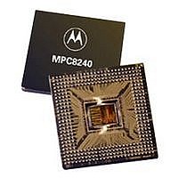
XPC8240RZU250E Freescale Semiconductor, XPC8240RZU250E Datasheet - Page 42

XPC8240RZU250E
Manufacturer Part Number
XPC8240RZU250E
Description
MCU HOST PROCESSOR 352-TBGA
Manufacturer
Freescale Semiconductor
Series
PowerQUICC IIr
Specifications of XPC8240RZU250E
Processor Type
MPC82xx PowerQUICC II 32-bit
Speed
200MHz
Voltage
2.5V
Mounting Type
Surface Mount
Package / Case
352-TBGA
Core Size
32 Bit
Program Memory Size
32KB
Cpu Speed
250MHz
Embedded Interface Type
I2C
Digital Ic Case Style
TBGA
No. Of Pins
352
Supply Voltage Range
2.5V To 2.75V
Rohs Compliant
No
Family Name
MPC82XX
Device Core Size
32b
Frequency (max)
250MHz
Instruction Set Architecture
RISC
Supply Voltage 1 (typ)
2.625/2.6255V
Operating Supply Voltage (max)
2.75625/2.756775V
Operating Supply Voltage (min)
2.49375/2.494225V
Operating Temp Range
0C to 105C
Operating Temperature Classification
Commercial
Mounting
Surface Mount
Pin Count
352
Package Type
TBGA
Lead Free Status / RoHS Status
Contains lead / RoHS non-compliant
Features
-
Lead Free Status / Rohs Status
Not Compliant
Available stocks
Company
Part Number
Manufacturer
Quantity
Price
Company:
Part Number:
XPC8240RZU250E
Manufacturer:
MOT
Quantity:
12 388
Company:
Part Number:
XPC8240RZU250E
Manufacturer:
MOTOLOLA
Quantity:
513
Company:
Part Number:
XPC8240RZU250E
Manufacturer:
Freescale Semiconductor
Quantity:
10 000
Part Number:
XPC8240RZU250E
Manufacturer:
FREESCALE
Quantity:
20 000
System Design Information
System Design Information
Ultimately, the final selection of an appropriate heat sink depends on many factors, such as thermal
performance at a given air velocity, spatial volume, mass, attachment method, assembly, and cost.
1.7.8.1
The intrinsic conduction thermal resistance paths for the TBGA, cavity-down, packaging technology shown
in Figure 26 are as follows:
Figure 28 depicts the primary heat transfer path for a package with an attached heat sink mounted to a
printed-circuit board.
For this cavity-down, wire-bond TBGA package, heat generated on the active side of the chip is conducted
through the silicon, die attach, and package spreader, through the heat sink attach material (or thermal
interface material), and finally to the heat sink, where it is removed by forced-air convection.
1.7.8.2
A thermal interface material is recommended at the package lid-to-heat sink interface to minimize thermal
contact resistance. For those applications where the heat sink is attached by a spring clip mechanism,
Figure 29 shows the thermal performance of three thin-sheet thermal-interface materials (silicone,
42
•
•
Tyco Electronics
Chip Coolers™
P.O. Box 3668
Harrisburg, PA 17105-3668
Internet: www.chipcoolers.com
Wakefield Engineering
33 Bridge St.
Pelham, NH 03076
Internet: www.wakefield.com
The die junction-to-case thermal resistance
The die junction-to-ball thermal resistance
Figure 28. TBGA Package with Heat Sink Mounted to a Printed-Circuit Board
(Note the internal versus external package resistance.)
Internal Package Conduction Resistance
Adhesives and Thermal Interface Materials
External Resistance
External Resistance
Internal Resistance
MPC8240 Integrated Processor Hardware Specifications
Freescale Semiconductor, Inc.
Printed-Circuit Board
For More Information On This Product,
Heat Sink
Go to: www.freescale.com
Radiation
Radiation
Convection
Convection
Thermal Interface Material
800-522-6752
603-635-5102
Die/Package
Die Junction
Package/Leads


