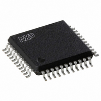
SC28L92A1B,557 NXP Semiconductors, SC28L92A1B,557 Datasheet - Page 29

SC28L92A1B,557
Manufacturer Part Number
SC28L92A1B,557
Description
IC UART DUAL W/FIFO 44-PQFP
Manufacturer
NXP Semiconductors
Series
IMPACTr
Type
Dual UARTr
Datasheet
1.SC28L92A1B557.pdf
(73 pages)
Specifications of SC28L92A1B,557
Number Of Channels
2, DUART
Package / Case
44-MQFP, 44-PQFP
Features
False-start Bit Detection
Fifo's
16 Byte
Voltage - Supply
3.3V, 5V
With Auto Flow Control
Yes
With False Start Bit Detection
Yes
With Modem Control
Yes
With Cmos
Yes
Mounting Type
Surface Mount
Data Rate
0.2304 MBd
Supply Voltage (max)
3.63 V or 5.5 V
Supply Voltage (min)
2.97 V or 4.5 V
Supply Current
25 mA
Maximum Operating Temperature
+ 85 C
Minimum Operating Temperature
- 40 C
Mounting Style
SMD/SMT
Operating Supply Voltage
3.3 V or 5 V
Lead Free Status / RoHS Status
Lead free / RoHS Compliant
Lead Free Status / RoHS Status
Lead free / RoHS Compliant, Lead free / RoHS Compliant
Other names
568-1211
935263294557
SC28L92A1B
935263294557
SC28L92A1B
Available stocks
Company
Part Number
Manufacturer
Quantity
Price
Company:
Part Number:
SC28L92A1B,557
Manufacturer:
NXP Semiconductors
Quantity:
10 000
NXP Semiconductors
Table 29.
MR2A is accessed when the channel A MR pointer points to MR2, which occurs after any access to MR1A. Accesses to
MR2A do not change the pointer.
SC28L92_7
Product data sheet
7
channel mode
MR2A - Mode Register 2 channel A (address 0x0) bit allocation
7.3.1.3 Mode Register 2 channel A (MR2A)
6
Table 28.
Table 30.
Bit
2
1:0
Bit
7 and 6
Control Tx
RTSN
Symbol
PARITYTYPE
-
Symbol
-
MR1A - Mode Register 1 channel A (address 0x0) bit description
MR2A - Mode Register 2 channel A (address 0x0) bit description
5
Rev. 07 — 19 December 2007
Enable Tx
Description
Channel A mode select. Each channel of the DUART can operate in one of
the following four modes:
Table 31
The user must exercise care when switching into and out of the various
modes. The selected mode will be activated immediately upon mode
selection, even if this occurs in the middle of a received or transmitted
character. Likewise, if a mode is deselected the device will switch out of the
mode immediately. An exception to this is switching out of auto echo or
remote loopback modes: if the deselection occurs just after the receiver
has sampled the stop bit (indicated in auto echo by assertion of RxRDY),
and the transmitter is enabled, the transmitter will remain in auto echo
mode until the entire stop has been retransmitted.
3.3 V/5.0 V Dual Universal Asynchronous Receiver/Transmitter
CTSN
00 = Normal mode (default)
01 = Automatic echo mode
10 = Local loopback mode
11 = Remote loopback mode
4
Description
Channel A parity type select
This bit selects the parity type (odd or even) if the with parity mode is
programmed by MR1A[4:3], and the polarity of the forced parity bit if
the force parity mode is programmed. It has no effect if the no parity
mode is programmed. In the special multi-drop mode it selects the
polarity of the A/D bit.
Channel A bits per character select.
This field selects the number of data bits per character to be
transmitted and received. The character length does not include the
start, parity, and stop bits.
0 = even
1 = odd
00 = 5 bits
01 = 6 bits
10 = 7 bits
11 = 8 bits
gives a description of the channel modes
3
2
stop bit length
1
SC28L92
© NXP B.V. 2007. All rights reserved.
…continued
0
29 of 73


