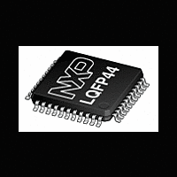
XA-C3 NXP Semiconductors, XA-C3 Datasheet - Page 32

XA-C3
Manufacturer Part Number
XA-C3
Description
The XA-C3 is a member of the Philips XA (eXtended Architecture) family of high-performance 16-bit single-chip microcontrollers
Manufacturer
NXP Semiconductors
Datasheet
1.XA-C3.pdf
(68 pages)
Philips Semiconductors
The XA–C3 supports 42 vectored interrupts. These include 13
maskable Event Interrupts, 7 Software Interrupts, 16 Trap interrupts,
and 6 Exception Interrupts. The number of Event Interrupts is
related to the number of on–chip peripherals. The XA–C3 supports
13 maskable Event Interrupts. However, Software, Trap, and
Exception Interrupts are standardized within the XA core. For core
details refer to the XA User Guide.
Interrupt Structures
Four tables provide details of the XA-C3 Interrupt structure.
Event Interrupt Handling
If a higher priority Event occurs while a lower priority Event is being
serviced, the higher priority Event takes over.
When Events of different priorities occur simultaneously, the highest
priority Event is serviced first.
When Events of equal priority occur simultaneously, Arbitration
Ranking determines which Event is serviced first. See Table 15 and
Table 16.
Interrupt Priority Details
Each Event interrupt has 8 priority levels. Event interrupts may be
individually masked by bits in SFR Registers IEL and IEH (see
Table 5). Event interrupts can also be globally disabled via the EA bit
(IEL[7]).
Table 15. Exception and Trap Interrupt Vectors
2000 Jan 25
Exception Interrupts – process non–maskable events, such as
Reset, Stack Overflow, and Divide–by–zero.
Table 14 defines the sixteen interrupt priority levels
Table 15 describes the Exception and Trap Interrupts
Table 16 explains the Event Interrupts
Table 17 lists the Software Interrupts
XA 16-bit microcontroller family
32K/1024 OTP CAN transport layer controller
1 UART, 1 SPI Port, CAN 2.0B, 32 CAN ID filters, transport layer co-processor
Reset (h/w, watchdog, s/w)
Breakpoint (h/w trap 1)
Trace (h/w trap 2)
Stack Overflow (h/w trap 3)
Divide by 0 (h/w trap 4)
User RETI (h/w trap 5)
TRAP 0– 15 (software)
DESCRIPTION
VECTOR ADDRESS
25
000C – 000F
0000 – 0003
0004 – 0007
0008 – 000B
0010 – 0013
0014 – 0017
0040 – 007F
1. Details of the priority scheme may be found in the XA User
Using 3–bit sub–groups, Interrupt Priority Assignment (IPA) registers
(IPA0, IPA1, IPA2, IPA4, IPA5, IPA6, and IPA7) assign 1 of 8 priority
levels per Event Interrupt. A zero value assigns interrupt priority 0, in
effect disabling an interrupt. The remaining seven priority levels are
defined in Table 14.
Table 14. Interrupt Priority Levels
NOTE:
Priority Level
15
14
13
12
11
10
9
8
7
6
5
4
3
2
1
0
Guide.
Type of Interrupt
Event Interrupt
Event Interrupt
Event Interrupt
Event Interrupt
Event Interrupt
Event Interrupt
Event Interrupt
Software Interrupt
Software Interrupt
Software Interrupt
Software Interrupt
Software Interrupt
Software Interrupt
Software Interrupt
Interrupt Disable
ARBITRATION RANKING
Preliminary specification
0 (High)
1
1
1
1
1
1
XA-C3


