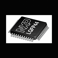
XA-C3 NXP Semiconductors, XA-C3 Datasheet - Page 60

XA-C3
Manufacturer Part Number
XA-C3
Description
The XA-C3 is a member of the Philips XA (eXtended Architecture) family of high-performance 16-bit single-chip microcontrollers
Manufacturer
NXP Semiconductors
Datasheet
1.XA-C3.pdf
(68 pages)
Philips Semiconductors
CAN Interrupt SFRs
As with all XA Event interrupts, the five CAN interrupts can be
independently enabled, disabled, and prioritized using the interrupt
Table 27. SFR Interrupt Enable/Priority Bit Positions
NOTE: ALSO SEE TABLE 25 ON PAGE 49
EMRI
EMTI
EMER
ECER
ESPI
ETI0, ERI0
EBUFF
EA, ET2, ET1, EX1, ET0, EX0
PX0, PT0, PX1, PT1, PT2
PBUFF
PRI0, PTI0
PSPI
PMRI
PMTI
PMER
PCER
POWER–DOWN AND IDLE MODE
Background: XA Power–Down and Idle modes
Power–Down mode on the XA means that the main oscillator is
clamped–off and there is no chip activity of any kind. I
is on the order of a few tens of microamps. Wake–up from
power–down is accomplished via a system reset or a transition on
the External Interrupt 0 or 1 pins. The wake–up period is 10,000
oscillator clocks (enough for several CAN frames to be transmitted).
Idle mode on the XA means that the clocks are running but are
gated–off to the processor core. Most peripherals are active, but
some may be put to sleep along with the core. Wake–up from Idle
2000 Jan 25
XA 16-bit microcontroller family
32K/1024 OTP CAN transport layer controller
1 UART, 1 SPI Port, CAN 2.0B, 32 CAN ID filters, transport layer co-processor
Name
IPA0
IPA1
IPA2
IPA4
IPA5
IPA6
IPA7
SFR
IEH
IEL
Address
SFR
427
426
4A0
4A1
4A2
4A4
4A5
4A6
4A7
Rx Message Complete interrupt
enable.
Tx Message Complete interrupt
enable.
Message Error interrupt enable.
Frame Error interrupt enable.
SPI Port Interrupt enable.
enable bits.
Rx Buffer Full interrupt enable.
XA-C3 Enable All, Timer, and
External interrupt enable bits.
XA-C3 External and Timer
interrupt priority fields.
Rx Buffer Full interrupt priority
field.
priority fields.
SPI Port interrupt priority field.
Rx Message Complete interrupt
priority field.
Tx Message Complete interrupt
priority field.
Message Error interrupt priority
field.
Frame Error interrupt priority field.
XA-C3 Serial Port 0 interrupt
XA-C3 Serial Port 0 interrupt
EMRI
Bit 7
EA
–
–
–
–
–
–
–
unused
dd
EMTI
Bit 6
in this mode
PBUFF
EBUFF
PMER
EMER
PMRI
PSPI
PTI0
PT0
PT1
Bit 5
53
control SFRs in the XA Core (see IEH, IEL, and IPA0 – IPA7 in Table
26 on page 50 and see Table 16 on page 26). Bit positions are given
below in .
mode is instantaneous, and is initiated via any interrupt. I
mode is in the range of 25–30 mA @ 32 MHz if the CAN/CTL
module is deactivated, perhaps 54–80 mA @ 32 MHz if the CAN is
left active. Note that putting the XA core, by itself, into Idle mode
reduces power consumption by approximately 30 mA @ 32MHz.
XA-C3 Idle Mode
The default condition for the CTL/CAN module will be to stay awake
in Idle mode, so that the core can “sleep” while CAN
transmissions/receptions are in progress. Any interrupt (e.g.,
Message Complete) will wake up the core. An option will be
provided to include the CAN/CTL module in Idle mode. This option
will be selected in software by writing to the SLPEN bit in MMR
CANCMR[3]. If the CAN does go to sleep in Idle mode, then any
transition on the CAN RxD input pin will be asynchronously latched
and will immediately re–enable the clocks to the CAN/CTL module
so that it can begin receiving the incoming frame. There will not be
any interrupt generated, however, and the processor core will
remain in idle mode. The CPU will only come out of Idle mode once
a complete message is received and stored and a
Message–Complete interrupt is generated (unless, of course, some
other system interrupt wakes it up prior to that). The CCB will
generate a “ccb_idle_n” signal which will be routed to all of the other
CAN/CTL blocks (including the CMI) at the top level.
XA-C3 Power–Down Mode
If a transition of the CAN RxD input occurs when the XA-C3 is in
Power–Down mode, the CPU will enter Idle mode (after a 9892
clock delay), and the CCB and Message Handler circuits will be
activated to receive and process the incoming frame. When either of
these blocks generates an interrupt (or some other enabled interrupt
occurs), only then will the CPU come out of Idle mode and begin
executing code. Code execution will resume either in the interrupt
service routine, if its priority is higher than current code, or with the
next instruction following the Power–Down instruction. At this time
the termination of the Power–Down mode is actually complete.
CAN Sleep Enable
Certain conditions must be met before the CAN/CTL module can be
safely put to sleep (Idle or Power–Down). Essentially, there must be
no CAN activity in progress and no interrupts pending. The CCB
must generate a “sleepok” signal (SLPOK=CANSTR[2]) which
indicates that these conditions are met. This signal must be used to
enable the “ccb_idle_n” signal. In addition, the “sleepok” signal
ECER
Bit 4
ET2
ESPI
Bit 3
ET1
–
–
–
–
–
–
–
unused
Bit 2
EX1
Preliminary specification
unused
PCER
PMTI
PRI0
PX0
PX1
PT2
Bit 1
ETI0
ET0
XA-C3
dd
ERI0
in Idle
Bit 0
EX0


