AMIS30622C6228G ON Semiconductor, AMIS30622C6228G Datasheet - Page 31

AMIS30622C6228G
Manufacturer Part Number
AMIS30622C6228G
Description
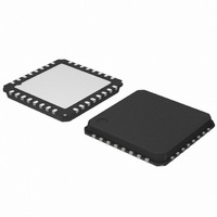
IC MOTOR DVR MICROSTP I2C 32NQFP
Manufacturer
ON Semiconductor
Type
Micro Stepping Motor Driverr
Datasheet
1.AMIS30622C6227RG.pdf
(50 pages)
Specifications of AMIS30622C6228G
Applications
Stepper Motor Driver
Number Of Outputs
1
Current - Output
800mA
Voltage - Supply
6.5 V ~ 29 V
Operating Temperature
-40°C ~ 125°C
Mounting Type
Surface Mount
Package / Case
32-VSQFP
Operating Supply Voltage
5 V
Mounting Style
SMD/SMT
Lead Free Status / RoHS Status
Lead free / RoHS Compliant
Voltage - Load
-
Lead Free Status / Rohs Status
Lead free / RoHS Compliant
Available stocks
Company
Part Number
Manufacturer
Quantity
Price
Company:
Part Number:
AMIS30622C6228G
Manufacturer:
ON Semiconductor
Quantity:
71
Company:
Part Number:
AMIS30622C6228G
Manufacturer:
ON Semiconductor
Quantity:
10 000
29. <ElFlag> = <CPFail> or <UV2> or <ElDef> or <VDDreset>
30. After power−on−reset, the <Standby> state is entered.
31. A DualPosition sequence runs with a separate set of RAM registers. The parameters that are not specified in a DualPosition command are
32. Shutdown state can be left only when <TSD> and <HS> flags are reset.
33. Flags can be reset only after the master could read them via a GetFullStatus1 command, and provided the physical conditions allow
34. A SetMotorParam command sent while a motion is ongoing (state <GotoPos>) should not attempt to modify <Acc> and <Vmin> values.
35. <SecEn> = ‘1’ when register <SecPos> is loaded with a value different from the most negative value (i.e. different from 0x400 = “100 0000
36. <Stop> flag allows distinguishing whether state <Stopped> was entered after HardStop/SoftStop or not. <Stop> is set to ‘1’ when leaving
37. While in state <Stopped>, if <ActPos> → <TagPos> there is a transition to state <GotoPos>. This transition has the lowest priority,
38. If <StepLoss> is active, then SetPosition and GotoSecurePosition commands are not ignored. <StepLoss> can only be cleared
loaded with the values stored in RAM at the moment the DualPosition sequence starts. <AccShape> is forced to ‘1’ during second motion.
<AccShape> at ‘0’ will be taken into account after the DualPosition sequence. A GetFullStatus1 command will return the default
parameters for <Vmax> and <Vmin> stored in RAM.
for it (normal temperature, correct battery voltage and no electrical or charge pump defect).
This can be done during a DualPosition sequence since this motion uses its own parameters, the new parameters will be taken into account
at the next SetPosition command.
0000”).
state <HardStop> or <SoftStop> and is reset during first clock edge occurring in state <Stopped>.
meaning that <Stop>, <TSD>, etceteras are first evaluated for possible transitions.
by a GetFullStatus1 command.
Shutdown
POR
Vbb < UV2 or CPFAIL
Thermal Shutdown
GetFullStatus1
HardStop
Dual Positioning Motion finished
Figure 17. Simplified State Diagram
http://onsemi.com
Referencing
Stopped
31
Priorities 1
HardStop
Motion Finished
Thermal Shutdown
Motion Finished
2
3
4
HardStop
GotoSecPos
SetPosition
Motion Finished
HardStop
HardStop
HardStop
Soft−stop
GotoPos
Vbb < UV2 or CPFAIL
ShutDown
SoftStop
Thermal


