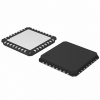
AMIS30622C6228G ON Semiconductor, AMIS30622C6228G Datasheet - Page 6

AMIS30622C6228G
Manufacturer Part Number
AMIS30622C6228G
Description
IC MOTOR DVR MICROSTP I2C 32NQFP
Manufacturer
ON Semiconductor
Type
Micro Stepping Motor Driverr
Datasheet
1.AMIS30622C6227RG.pdf
(50 pages)
Specifications of AMIS30622C6228G
Applications
Stepper Motor Driver
Number Of Outputs
1
Current - Output
800mA
Voltage - Supply
6.5 V ~ 29 V
Operating Temperature
-40°C ~ 125°C
Mounting Type
Surface Mount
Package / Case
32-VSQFP
Operating Supply Voltage
5 V
Mounting Style
SMD/SMT
Lead Free Status / RoHS Status
Lead free / RoHS Compliant
Voltage - Load
-
Lead Free Status / Rohs Status
Lead free / RoHS Compliant
Available stocks
Company
Part Number
Manufacturer
Quantity
Price
Company:
Part Number:
AMIS30622C6228G
Manufacturer:
ON Semiconductor
Quantity:
71
Company:
Part Number:
AMIS30622C6228G
Manufacturer:
ON Semiconductor
Quantity:
10 000
currents flowing into the circuit are defined as positive.
4. Tested in production for 800 mA, 400 mA, 200 mA and 100 mA current settings for both X and Y coil.
5. Not measured in production. Guaranteed by design.
6. Parameter guaranteed by trimming relevant OTP’s in production test at 143°C (±5°C) and V
7. No more than 100 cumulated hours in life time above Tw.
8. Thermal shutdown and low temperature warning are derived from thermal warning. Guaranteed by design.
9. A buffer capacitor of minimum 100 mF is needed between V
10. If input voltages < − 0.3 V, than a resistor between 22 W to 100 W needs to be put in series.
11. If the I
MOTORDRIVER
I
THERMAL WARNING & SHUTDOWN
SUPPLY AND VOLTAGE REGULATOR
I
I
Table 5. DC PARAMETERS
2
MSmax,Peak
MSmax,RMS
C SERIAL INTERFACE
The DC parameters are guaranteed overtemperature and V
Symbol
R
V
I
I
MSabs
I
bbOTP
MSrel
DS(on)
V
T
UV
UV
V
T
V
T
I
MSL
V
bat
low
nH
tsd
nL
IH
tw
IL
1
2
2
C−bus is operated in Fast Mode V
MOTXN
MOTYN
MOTXP
MOTYP
Pin(s)
SDA
SCK
V
BB
Max current through motor coil
in normal operation
Max rms current through coil in
normal operation
Absolute error on coil
current (Note 4)
Matching of X & Y
coil currents
On resistance for each
motor pin at I
(Note 5)
Pulldown current
Input level low (Note 10)
Input level high (Note 11)
Noise margin at the LOW level
for each connected device
(including hysteresis)
Noise margin at the HIGH level
for each connected device
(including hysteresis)
Thermal warning
(Notes 6 and 7)
Thermal shutdown (Note 8)
Low temperature warning (Note
8)
Supply voltage for OTP
zapping (Note 9)
Stop voltage high threshold
Stop voltage low threshold
Total current consumption
Parameter
MSmax
IHmin
= 0.7 * V
DC PARAMETERS
http://onsemi.com
DD
V
HiZ mode, V
.
V
V
V
BB
BB
BB
BB
Unloaded outputs
BB
Test Conditions
= 12 V, T
and GND. Short connections to the power supply are recommended.
= 12 V, T
= 8 V, T
BB
V
V
V
V
= 8 V, T
V
BB
BB
BB
BB
BB
6
in the operating range, unless otherwise specified. Convention:
= 14 V
= 14 V
= 14 V
= 14 V
= 29 V
BB
j
j
j
= 150°C
j
= 50°C
= 150°C
= 50°C
= 7.8 V
0.7 * V
0.1 * V
0.2 * V
−0.5
Min
−10
138
9.0
7.7
7.0
−7
BB
DD
DD
DD
= 14 V.
T
T
tw
tw
0.50
0.55
0.70
0.85
3.50
Typ
800
570
145
8.3
7.5
− 155
0
2
+ 10
V
0.3 * V
DD
Max
10.0
10.0
152
8.9
8.0
10
7
1
1
1
1
+ 0.5
DD
Unit
mA
mA
mA
mA
°C
°C
°C
%
%
W
W
W
W
V
V
V
V
V
V


