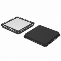
AMIS30622C6228G ON Semiconductor, AMIS30622C6228G Datasheet - Page 33

AMIS30622C6228G
Manufacturer Part Number
AMIS30622C6228G
Description
IC MOTOR DVR MICROSTP I2C 32NQFP
Manufacturer
ON Semiconductor
Type
Micro Stepping Motor Driverr
Datasheet
1.AMIS30622C6227RG.pdf
(50 pages)
Specifications of AMIS30622C6228G
Applications
Stepper Motor Driver
Number Of Outputs
1
Current - Output
800mA
Voltage - Supply
6.5 V ~ 29 V
Operating Temperature
-40°C ~ 125°C
Mounting Type
Surface Mount
Package / Case
32-VSQFP
Operating Supply Voltage
5 V
Mounting Style
SMD/SMT
Lead Free Status / RoHS Status
Lead free / RoHS Compliant
Voltage - Load
-
Lead Free Status / Rohs Status
Lead free / RoHS Compliant
Available stocks
Company
Part Number
Manufacturer
Quantity
Price
Company:
Part Number:
AMIS30622C6228G
Manufacturer:
ON Semiconductor
Quantity:
71
Company:
Part Number:
AMIS30622C6228G
Manufacturer:
ON Semiconductor
Quantity:
10 000
Motor Starting Phase
switched from <Ihold> to <Irun> with a new
sine/cosine ratio corresponding to the first half (or micro−)
step of the motion.
Charge Pump Monitoring
high side transistors (due to failure), an internal HardStop
command is issued. This is acknowledged to the master by
raising flag <CPFail> (available with command
GetFullStatus1).
flag <StepLoss> is also raised.
Electrical Defect on Coils, Detection and Confirmation
at least one transistor of the H−bridge. Then the decision is
taken to open the transistors of the defective bridge.
This allows the detection the following short circuits:
•
•
One cannot detect an internal short in the motor.
value during one electrical period with duration, determined
by Vmin.
Table 22. ELECTRICAL DEFECT DETECTION
Yi or Xi
Yi or Xi
Yi or Xi
Y1 and Y2
X1 and X2
Xi and Yi
At motion start, the currents in the coils are directly
If the charge pump voltage is not sufficient for driving the
In case this failure occurs while a motion is ongoing, the
The principle relies on the detection of a voltage drop on
Open circuits are detected by 100% PWM duty cycle
External coil short circuit
Short between one terminal of the coil and Vbat or GND
Pins
Iy
Ix
Short−circuit to GND
Short−circuit to Vbat
Open
Short circuited
Short circuited
Short circuited
Fault Mode
Figure 20. Motor Stopping Phase
http://onsemi.com
33
Motor Stopping Phase
maintained in the coils at their actual DC level (hence
keeping the sine/cosine ratio between coils) during the
stabilization time t
set to the hold values, respectively Ihold x sin(TagPos)
and Ihold x cos(TagPos), as illustrated below. A new
positioning order can then be executed.
Motor Shutdown Mode
A motor shutdown occurs when:
•
•
•
•
A motor shutdown leads to the following:
•
•
The conditions to get out of a motor shutdown mode are:
•
•
This leads to H−bridges going in Ihold mode. Hence, the
circuit is ready to execute any positioning command.
At the end of the deceleration phase, the currents are
The chip temperature rises above the thermal shutdown
threshold Ttsd (see Thermal Shutdown Mode).
The battery voltage goes below UV2 for longer than 15
seconds (see Battery Voltage Management).
The charge pump voltage goes below the charge pump
comparator level for more than 15 seconds.
Flag <ElDef> = ‘1’, meaning an electrical problem is
detected on one or both coils, e.g. a short circuit.
H−bridges in high impedance mode.
The <TagPos> register is loaded with the <ActPos>,
except in autarkic states.
Reception of a GetFullStatus1 command AND
The four above causes are no longer detected
stab
(see AC Table). The currents are then
t stab
t


