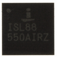
ISL88550AIRZ Intersil, ISL88550AIRZ Datasheet - Page 18

ISL88550AIRZ
Manufacturer Part Number
ISL88550AIRZ
Description
IC PWM CONTROLLER 28TQFN
Manufacturer
Intersil
Datasheet
1.ISL88550AIRZ.pdf
(25 pages)
Specifications of ISL88550AIRZ
Applications
PWM Controller
Voltage - Input
2 ~ 25 V
Current - Supply
25µA
Operating Temperature
-40°C ~ 85°C
Mounting Type
Surface Mount
Package / Case
28-TQFN
Rohs Compliant
YES
Lead Free Status / RoHS Status
Lead free / RoHS Compliant
Voltage - Supply
-
Available stocks
Company
Part Number
Manufacturer
Quantity
Price
Company:
Part Number:
ISL88550AIRZ
Manufacturer:
Intersil
Quantity:
480
Part Number:
ISL88550AIRZ
Manufacturer:
INTERSIL
Quantity:
20 000
Company:
Part Number:
ISL88550AIRZ-T
Manufacturer:
AMD
Quantity:
2
Part Number:
ISL88550AIRZ-T
Manufacturer:
INTERSIL
Quantity:
20 000
Setting the Buck Regulator Output (V
Resistive Voltage-Divider at FB
The Buck Regulator output voltage can be adjusted from
0.7V to 3.5V using a resistive voltage-divider (Figure 26).
The ISL88550A regulates FB to a fixed reference voltage
(0.7V). The adjusted output voltage is shown in Equation 6:
Where VFB is 0.7V and Equation 7 is:
Setting the VTT and VTTR Voltages (LDO)
The Termination Power Supply Output (VTT) can be set by
two different methods. First, the VTT output can be
connected directly to the VTTS input to force VTT to regulate
to V
V
V
0.1 x REF
FIGURE 26. SETTING V OUT WTH A RESISTIVE VOLTAGE
OUT
RIPPLE
(0.2V)
REFIN
FB
=
ISL88550A
V
FIGURE 25. DUAL-MODE FEEDBACK DECODER
=
FB
LIR
⎛
⎜
⎜
⎝
PHASE
PGND1
/2. Second, VTT can be forced to regulate higher
1
LGATE
+
×
GND
AMPLIFIER
OUT
TO ERROR
I
R
LOAD
R
DIVIDER
FB
+
-
C
D
⎞
⎟
⎟
⎠
+
×
R
V
ESR
RIPPLE
2
Q2
18
ISL88550A
L
OUT
R C
R D
) with a
+
2.5V (FIXED)
C OUT
OUT
(EQ. 6)
(EQ. 7)
ISL88550A
than V
VTTS.
For cases where resistor divider programming is desired, a
special set of equations must be used to determine the
proper resistance values:
Where KVTOL is the desired accuracy of the VTT voltage in
percent (e.g. - for 0.5%, KVTOL = 0.5).
The maximum value for VTT will be the V
where V
The Termination Reference Voltage (VTTR) will follow ½
V
Inductor Selection (Buck)
The switching frequency and inductor operating point
determine the inductor value, as shown in Equation 10:
For example: I
ƒ
Equation 11.
Find a low-loss inductor having the lowest possible DC
resistance that fits in the allotted dimensions. Ferrite cores
are often the best choice, although powdered iron is
inexpensive and can work well at 200kHz. The core must be
large enough not to saturate at the peak inductor current
(I
R
R
FIGURE 27. RESISTOR DIVIDER PROGRAMMING OF VTT LDO
L
L
I
PEAK
SW
PEAK
REFIN
1
2
=
=
12
=
=
V
= 300kHz, 30% ripple current or LIR = 0.3, as shown in
IN
=
V
V
--------------------------------- -
R
I
REFIN
×
2
) as shown in Equation 12:
LOAD
V
×
TT
1
.
f
5 .
SW
DROPOUT
OUT
300
6
⋅
V
×10
⋅
------------------------------------------------------------------------------ -
(
(
(
MAX
12
2
×
K
(
kHz
V
×10
I
LOAD
VTOL
/2 by connecting a resistive divider from VTT to
IN
V
–
)
4
⎛
⎜ ⎜
⎝
−
LOAD(MAX)
−
×
1
–
2
12
+
V
(
5
MAX
5 .
OUT
LIR
⋅
A
2
V
R
REFIN
VTTI
= I
)
×
)
×
REFIN
-------------------
ISL88550A
)
1
⎞
⎟ ⎟
⎠
0
LIR
)
3 .
VTT
+
2
=
V
1
VTTS
TT
8 .
× 0.3 typically.
VTT
= 12A, V
µH
–
REFIN
-------------------
2
IN
= 12V, V
R1
R2
VTTI
OUT
- V
DROPOUT
April 23, 2008
= 2.5V,
(EQ. 10)
(EQ. 12)
(EQ. 11)
FN6168.3
(EQ. 8)
(EQ. 9)


