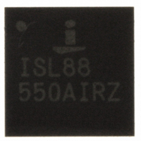
ISL88550AIRZ Intersil, ISL88550AIRZ Datasheet - Page 5

ISL88550AIRZ
Manufacturer Part Number
ISL88550AIRZ
Description
IC PWM CONTROLLER 28TQFN
Manufacturer
Intersil
Datasheet
1.ISL88550AIRZ.pdf
(25 pages)
Specifications of ISL88550AIRZ
Applications
PWM Controller
Voltage - Input
2 ~ 25 V
Current - Supply
25µA
Operating Temperature
-40°C ~ 85°C
Mounting Type
Surface Mount
Package / Case
28-TQFN
Rohs Compliant
YES
Lead Free Status / RoHS Status
Lead free / RoHS Compliant
Voltage - Supply
-
Available stocks
Company
Part Number
Manufacturer
Quantity
Price
Company:
Part Number:
ISL88550AIRZ
Manufacturer:
Intersil
Quantity:
480
Part Number:
ISL88550AIRZ
Manufacturer:
INTERSIL
Quantity:
20 000
Company:
Part Number:
ISL88550AIRZ-T
Manufacturer:
AMD
Quantity:
2
Part Number:
ISL88550AIRZ-T
Manufacturer:
INTERSIL
Quantity:
20 000
Electrical Specifications
NOTES:
Input Bias Current (FB)
Four-Level Input Logic Levels
(t
Logic Input Current (t
OUT Input Resistance
OUT Discharge Mode ON-Resistance
LINEAR REGULATORS (VTTR AND VTT)
VTTI Input Voltage Range
VTTI Supply Current
VTTI Shutdown Current
REFIN Input Impedance
REFIN Range
VTT, VTTR UVLO Threshold (Measured at
OUT)
Soft-Start Charge Current
VTT internal MOSFET High-Side
ON-Resistance
VTT internal MOSFET Low-Side
ON-Resistance
VTT Output Accuracy (Referenced to VTTR)
VTT Load Regulation
VTT Positive Current Limit
VTT Negative Current Limit
VTTS Input Current
VTTR Output Error (Referenced to V
VTTR Current Limit
4. Limits established by characterization and are not production tested.
5. When the inductor is in continuous conduction, the output voltage will have a DC regulation level higher than the error comparator threshold by
6. On-time and off-time specifications are measured from 50% point to 50% point at the UGATE pin with PHASE = GND, V
ON
50% of the ripple. In discontinuous conduction, the output voltage will have a DC regulation level higher than the trip level by approximately 1.5%
due to slope compensation.
capacitor connected from UGATE to PHASE. Actual in-circuit times may differ due to MOSFET switching speeds.
, OVP/UVP)
PARAMETER
ON
, OVP/UVP, Note 5)
5
V
FB = SKIP# = OVP/UVP = GND. PGND1 = PGND2 = PHASE = GND, VTTS = VTT, t
+85°C, Unless otherwise specified, parts are 100% tested at +25°C. Temperature limits established by
characterization and are not production tested. (Note 4). (Continued)
IN
REFIN
= +15V, V
/2) V
High
Floating
REF
Low
FB = GND
FB Adjustable Mode
I
SHDNA# = STBY# = GND
V
V
I
(T
I
V
V
V
VTT = 0
VTT = VTTI
V
VTTR = 0 or VTTI
VTT
VTT
VTT
DD
REFIN
SS
REFIN
REFIN
REFIN
VTTS
REFIN
J
= +125°C)
= AV
= 0
= I
= -100mA, V
= 100mA, AV
= 1.5V, VTT Open
VTTR
= 1.8V, I
= 2.5V
= 1.8V or 2.5V, I
= 2.5V, I
= 1.8V, I
DD
= SHDNA# = STBY# = BOOT = ILIM = 5V, OUT = REFIN = VTTI = 2.5V,
= 0
VTTR
VTT
VTT
ISL88550A
CONDITIONS
VTTI
DD
= 0A to ±1.5A
= 0A to ±1.5A
= 4.5V (T
= 0mA
= 1.5V, AV
VTT
= ±5mA
J
= +125°C)
DD
= 4.5V
AV
DD
-1.25
3.15
1.65
0.01
MIN
-0.1
-1.5
-3.5
125
125
±20
1.0
1.0
2.5
17
-3
- 0.4
TYP
0.10
0.18
-2.5
250
250
±40
0.1
0.1
3.0
0.1
15
20
4
1
1
ON
BOOT
= OPEN, T
MAX
3.85
2.35
0.28
0.43
1.25
500
500
-2.0
= 5V, and a 250pF
±60
0.1
0.5
2.8
2.8
0.2
1.5
4.0
+3
30
10
27
1
1
A
April 23, 2008
= -40°C to
FN6168.3
UNIT
mA
mA
µA
µA
kΩ
kΩ
µA
kΩ
µA
µA
%
%
%
%
V
V
V
V
Ω
V
V
V
Ω
Ω
A
A


