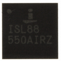
ISL88550AIRZ Intersil, ISL88550AIRZ Datasheet - Page 7

ISL88550AIRZ
Manufacturer Part Number
ISL88550AIRZ
Description
IC PWM CONTROLLER 28TQFN
Manufacturer
Intersil
Datasheet
1.ISL88550AIRZ.pdf
(25 pages)
Specifications of ISL88550AIRZ
Applications
PWM Controller
Voltage - Input
2 ~ 25 V
Current - Supply
25µA
Operating Temperature
-40°C ~ 85°C
Mounting Type
Surface Mount
Package / Case
28-TQFN
Rohs Compliant
YES
Lead Free Status / RoHS Status
Lead free / RoHS Compliant
Voltage - Supply
-
Available stocks
Company
Part Number
Manufacturer
Quantity
Price
Company:
Part Number:
ISL88550AIRZ
Manufacturer:
Intersil
Quantity:
480
Part Number:
ISL88550AIRZ
Manufacturer:
INTERSIL
Quantity:
20 000
Company:
Part Number:
ISL88550AIRZ-T
Manufacturer:
AMD
Quantity:
2
Part Number:
ISL88550AIRZ-T
Manufacturer:
INTERSIL
Quantity:
20 000
Typical Operating Characteristics
Pin Descriptions
100
90
80
70
60
50
40
30
20
10
FIGURE 1. EFFICIENCY vs LOAD (1.8V) (t
0
0.001
PIN
19
20
21
22
23
24
25
26
27
28
25V
IN
12V
- SKIP
IN
- SKIP
0.010
3V
SHDNA#
PGND1
PHASE
LGATE
IN
NAME
BOOT
SKIP#
AVDD
VDD
GND
TP0
- SKIP
(Continued)
LOAD (A)
7
0.100
External Inductor Connection. Connect PHASE to the input side of the inductor. PHASE is used for both
current limit and the return supply of the UGATE driver.
Boost Flying-Capacitor Connection. Connect to an external capacitor according to the "Typical Application
Circuit" on page 22 (Figure 29). See “Boost-Supply Capacitor Selection (Buck)” on page 21.
Synchronous Rectifier Gate-Driver Output. Swings from PGND to V
Supply Input for the LGATE Gate Drive. Connect to +4.5V to +5.5V system supply voltage. Bypass to
PGND1 with a 4.7µF ceramic capacitor.
Power Ground for BUCK Controller. Connect PGND1 externally to the underside of the exposed pad.
Analog Ground for both BUCK and LDO. Connect externally to the underside of the exposed pad.
Pulse-Skipping Control Input. Connect to AV
enable pulse-skipping operation.
Analog Supply for both BUCK and LDO. Bypass to GND with a 1.0µF ceramic capacitor. A 10Ω internal
resistor is connected between V
Shutdown Control Input A. Use to control Buck output. A rising edge on SHDNA# clears the overvoltage
and undervoltage protection fault latches (see Tables 2 and 3). Connect AV
Test Pin. Must be connected to GND externally.
25V
1.000
3V
12V
IN
IN
ON
IN
- PWM
- PWM
- PWM
= GND)
V
unless otherwise noted.
IN
10.000
= 12V, V
ISL88550A
DDQ
DD
= 1.8V, t
and AV
FIGURE 2. SWITCHING FREQUENCY vs LOAD (t
DD
ON
700
600
500
400
300
200
100
DD
.
0
0.001
FUNCTION
= GND, SKIP# = AV
for low-noise, forced-PWM mode. Connect to GND to
12V
25V
3V
0.010
IN
IN
IN
- PWM
- PWM
- PWM
25V
DD
DD
3V
IN
12V
.
, circuit of Figure 29, T
-SKIP
IN
LOAD (A)
0.100
- SKIP
IN
DD
- SKIP
for normal operation.
1.000
A
ON
= +25°C,
April 23, 2008
= GND)
FN6168.3
10.000


