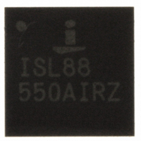
ISL88550AIRZ Intersil, ISL88550AIRZ Datasheet - Page 21

ISL88550AIRZ
Manufacturer Part Number
ISL88550AIRZ
Description
IC PWM CONTROLLER 28TQFN
Manufacturer
Intersil
Datasheet
1.ISL88550AIRZ.pdf
(25 pages)
Specifications of ISL88550AIRZ
Applications
PWM Controller
Voltage - Input
2 ~ 25 V
Current - Supply
25µA
Operating Temperature
-40°C ~ 85°C
Mounting Type
Surface Mount
Package / Case
28-TQFN
Rohs Compliant
YES
Lead Free Status / RoHS Status
Lead free / RoHS Compliant
Voltage - Supply
-
Available stocks
Company
Part Number
Manufacturer
Quantity
Price
Company:
Part Number:
ISL88550AIRZ
Manufacturer:
Intersil
Quantity:
480
Part Number:
ISL88550AIRZ
Manufacturer:
INTERSIL
Quantity:
20 000
Company:
Part Number:
ISL88550AIRZ-T
Manufacturer:
AMD
Quantity:
2
Part Number:
ISL88550AIRZ-T
Manufacturer:
INTERSIL
Quantity:
20 000
Setting the Current Limit (Buck)
The current-sense method used in the ISL88550A makes
use of the ON-resistance (r
(Q
calculating the current limit, use the worst-case maximum
value for r
some margin for the rise in r
good general rule is to allow 0.5% additional resistance for
each +1°C of temperature rise.
The minimum current-limit threshold must be great enough
to support the maximum load current when the current limit
is at the minimum tolerance value. The valley of the inductor
current occurs at I
as shown in Equation 25:
where I
threshold voltage divided by the ON-resistance of Q
(r
valley current-limit threshold is 40mV. Connect I
for a default 50mV valley current limit threshold. In
adjustable mode, the valley current limit threshold is
precisely 1/10th the voltage seen at I
threshold, connect a resistive divider from REF to GND with
I
adjustment range corresponds to a 25mV to 200mV valley
current-limit threshold. When adjusting the current limit, use
1% tolerance resistors and a divider current of approximately
10µA to prevent significant inaccuracy in the valley current
limit tolerance.
Setting the Foldback Current Limit (Buck)
Alternately, foldback current limit can be implemented if UVP
is disabled. Foldback current limit reduces the power
dissipation of external components so they can withstand
indefinite output overload or short circuit. With automatic
recovery after the fault condition is removed. To implement
foldback current limit, connect a resistor from V
(R
addition to the resistor-divider network (R
setting the adjustable current limit.
Equations 26 through 31 demonstrate how to calculate the
values of R
V
I
LIM
LIM
1. Calculate the voltage, V
2. Pick a percentage of foldback, P
DS(ON)Q2
ILIM
1
2
(
VAL
in the "Typical Application Circuit" on page 22), in
in "Typical Application Circuit" on page 22). When
connected to the center tap. The external 250mV to 2V
=
)
10
>
LIM(VAL)
I
×
LOAD
I
DS(ON)
LOAD
1
). For the 50mV default setting, the minimum
(
MAX
, R
(
MAX
)
4
−
equals the minimum valley current-limit
, and R
)
⎛
⎜
⎜
⎝
from the MOSFET data sheet, and add
×
LOAD(MAX)
I
LOAD
⎡
⎢
⎣
1
−
(
MAX
LIR
2
5
2
:
)
×
⎤
⎥
⎦
DS(ON)
LIR
×
ILIM
DS(ON)
r
21
DSON
minus half the ripple current,
⎞
⎟
⎟
⎠
(
Q
) 2
) of the low side MOSFET
with temperature. A
FB
LIM
, from 15% to 40%.
. For an adjustable
4
and R
OUT
LIM
5
) used for
to AV
2
to I
(EQ. 25)
(EQ. 26)
LIM
DD
ISL88550A
Boost-Supply Capacitor Selection (Buck)
The boost capacitor should be 0.1µF to 4.7µF, depending on
the input and output voltages, external components, and PC
board layout. The boost capacitance should be as large as
possible to prevent it from charging to excessive voltage, but
small enough to adequately charge during the minimum
low-side MOSFET conduction time, which happens at
maximum operating duty cycle (this occurs at minimum input
voltage). In addition, ensure that the boost capacitor does
not discharge to below the minimum gate-to-source voltage
required to keep the high-side MOSFET fully enhanced for
lowest ON-resistance. This minimum gate to source voltage
(V
where V
MOSFET, and C
C
page 22.
R
R
R
R
V
V
3. Calculate the voltage,V
4. The value of R
5. The parallel combination of R
6. Then R
7. Then R
1
BOOST
ILIM
4
R
5
GS
GS(MIN)
1
=
=
=
//
(
shorted (0V).
Equation 29:
MIN
0 (
R
[
[
R
R
2
5
(
V
VDDQ
V
5
5
)
)
=
×
−
=
=
−
10
10
DD
R
R
P
V
V
2
is C
FB
R
R
DD
ISL88550A/
ISL88550A/
ISL88551A
ISL88551A
μ
V
μ
) is determined using Equation 32:
FIGURE 28. FOLDBACK CURRENT LIMIT
ILIM
1
1
ISL88550A
A
5
1
A
−
//
//
is 5V, Q
×
×
R
R
(
V
0 (
can be calculated as:
V
is calculated as shown in Equation 31:
−
5
5
7
C
ILIM
V
ILIM
]
R
BOOST
)
in the "Typical Application Circuit" on
Q
4
GND
GND
BOOST
G
REF
REF
ILIM
ILIM
−
GND
REF
ILIM
4
V
G
ILIM
VDDQ
can be calculated using Equation 28:
is the total gate charge of the high-side
0 (
V
is the boost capacitor value where
)
)
)
×
×
VILIM(0V)
R
R
4
C
C
4
C
×
−
REF
REF
REF
R
(
V
R
1
1
ILIM
//
and R
R
5
, when the output is
−
V
R5
R5
ILIM
R4
R4
R4
5
0 (
is calculated using
R1
R1
V
R1
)
)
×
VDDQ
VDDQ
VDDQ
R
R
1
//
R
5
April 23, 2008
]
(EQ. 28)
(EQ. 27)
(EQ. 29)
(EQ. 30)
(EQ. 31)
(EQ. 32)
FN6168.3


