CY8CKIT-001 Cypress Semiconductor Corp, CY8CKIT-001 Datasheet - Page 59
CY8CKIT-001
Manufacturer Part Number
CY8CKIT-001
Description
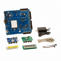
KIT DEV FOR PSOC3/5
Manufacturer
Cypress Semiconductor Corp
Series
PSoC® CapSenser
Type
MCUr
Datasheets
1.CY8CKIT-001.pdf
(2 pages)
2.CY8CKIT-001.pdf
(5 pages)
3.CY8CKIT-001.pdf
(116 pages)
4.CY8CKIT-001.pdf
(12 pages)
Specifications of CY8CKIT-001
Contents
Board, CD, CY8C29 & CY8C38 Modules, MiniProg3 Programmer/Debugger, Power Supply
Processor To Be Evaluated
CY8C29, CY8C38
Interface Type
RS-232, USB, JTAG
Operating Supply Voltage
3.3 V, 5 V
Lead Free Status / RoHS Status
Lead free / RoHS Compliant
For Use With/related Products
PSoC 1, PSoC 3 and PSoC 5
Lead Free Status / Rohs Status
Lead free / RoHS Compliant
Other names
428-2961
Available stocks
Company
Part Number
Manufacturer
Quantity
Price
Company:

Part Number:
CY8CKIT-001A
Manufacturer:
Cypress Semiconductor
Quantity:
135


3.2.1.8
3.2.2
3.2.2.1
CY8CKIT-001 PSoC Development Kit Guide, Doc. # 001-48651 Rev. **
}
/* [] END OF FILE */
3. From the Build menu, select Build Ex1_LED_with_PWM.
4. PSoC Creator builds the project and displays the comments in the Output dialog box. When you
Configuring and Programming the PSoC Development Board
1. Disconnect the power to the board.
2. Configure the DVK bread board SW3 to 3.3V.
3. Configure the following on the PSoC Development Board's prototyping area using the included
4. Apply power to the board.
5. Use PSoC Creator as described in
6. After programming the device, press the Reset button on the PSoC Development Board. The
7. Save and close the project.
ADC to LCD Project
This project demonstrates the Delta Sigma ADC by measuring the voltage of the potentiometer on
the board and displays the result on the Character LCD of the PSoC Development Board.
The ADC is clocked by the internal clock of 3 MHz and the sampling rate is set to 10,000 sps. Con-
nect the voltage potentiometer (labeled “VR” on the PSoC Development Board) to the ADC input
(programmed to P0[7] for this example). The program reads the ADC result and prints it to the LCD.
The instructions that follow assume that the user has completed My First PSoC Project and there-
fore has a basic understanding of the PSoC Creator software environment.
This example project uses these components:
■
■
■
Creating ADC to LCD Project
1. Open PSoC Creator.
2. Create a new project by clicking Create New Project… in the Start Page of PSoC Creator.
3. In the New Project window, select the Empty PSoC3 Design template and Name the project
4. In Location, type the path where you want to save the project, or click
see the message “Build Succeeded” the build is complete.
jumper wires
❐
❐
PWM causes the LED1 to blink at approximately 1 Hz due to PSoC Creator's PWM component
and LED2 blinks at a slower rate using a software timing loop to toggle the LED.
Delta Sigma ADC (Component Catalog
Character LCD (Component Catalog
Analog Port (Component Catalog
Ex2_ADC_to_LCD.
appropriate directory.
}
P1[6] to LED1
P1[7] to LED2
ledState ^= 0x01u;
LED_Write(ledState); /* Set the LED */
/* Toggle LED setting between low and high */
Programming a Device on page 15
→
System
→
→
Display
Analog
→
Analog Port)
→
→
Character LCD)
ADC
→
Delta Sigma ADC)
to program the device.
and navigate to the
Sample Projects
55
[+] Feedback
Related parts for CY8CKIT-001
Image
Part Number
Description
Manufacturer
Datasheet
Request
R

Part Number:
Description:
KIT DEV FOR PSOC3/5
Manufacturer:
Cypress Semiconductor Corp
Datasheet:

Part Number:
Description:
PSoC1/3/5 Development Kit
Manufacturer:
Cypress Semiconductor Corp
Datasheet:

Part Number:
Description:
KIT DEV PSOC PROC MODULE CY8C38
Manufacturer:
Cypress Semiconductor Corp

Part Number:
Description:
KIT DEV PSOC PROC MODULE CY8C29
Manufacturer:
Cypress Semiconductor Corp

Part Number:
Description:
KIT DEV PSOC ANALOG VOLTMETER
Manufacturer:
Cypress Semiconductor Corp
Datasheet:

Part Number:
Description:
KIT DEV PSOC5 FIRST TOUCH
Manufacturer:
Cypress Semiconductor Corp
Datasheet:

Part Number:
Description:
KIT DEV PSOC3 FIRSTTOUCH STARTER
Manufacturer:
Cypress Semiconductor Corp
Datasheet:
Part Number:
Description:
KIT DEV PROC MODULE PSOC5
Manufacturer:
Cypress Semiconductor Corp
Datasheet:

Part Number:
Description:
KIT PSOC CY8C28 FAMILY PROCESSOR
Manufacturer:
Cypress Semiconductor Corp
Datasheet:

Part Number:
Description:
KIT PSOC MINIPROG3 PROGRAM DEBUG
Manufacturer:
Cypress Semiconductor Corp
Datasheet:

Part Number:
Description:
KIT EVAL POWERLINE HIGH VOLT
Manufacturer:
Cypress Semiconductor Corp
Datasheet:

Part Number:
Description:
KIT PSOC FIRST TOUCH
Manufacturer:
Cypress Semiconductor Corp
Datasheet:

Part Number:
Description:
EVAL KIT WORLDTOUR2
Manufacturer:
Cypress Semiconductor Corp
Datasheet:

Part Number:
Description:
KIT UNIVERSAL CAPSENSE CTRLR
Manufacturer:
Cypress Semiconductor Corp
Datasheet:
