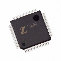
Z8F3222AR020SG Zilog, Z8F3222AR020SG Datasheet - Page 124

Z8F3222AR020SG
Manufacturer Part Number
Z8F3222AR020SG
Description
IC ENCORE MCU FLASH 32K 64LQFP
Manufacturer
Zilog
Series
Encore!® XP®r
Specifications of Z8F3222AR020SG
Core Processor
Z8
Core Size
8-Bit
Speed
20MHz
Connectivity
I²C, IrDA, SPI, UART/USART
Peripherals
Brown-out Detect/Reset, DMA, POR, PWM, WDT
Number Of I /o
46
Program Memory Size
32KB (32K x 8)
Program Memory Type
FLASH
Ram Size
2K x 8
Voltage - Supply (vcc/vdd)
3 V ~ 3.6 V
Data Converters
A/D 12x10b
Oscillator Type
Internal
Operating Temperature
0°C ~ 70°C
Package / Case
64-LQFP
Processor Series
Z8F322x
Core
eZ8
Data Bus Width
8 bit
Data Ram Size
2 KB
Interface Type
I2C, SPI, UART
Maximum Clock Frequency
20 MHz
Number Of Programmable I/os
46
Number Of Timers
4
Operating Supply Voltage
3 V to 3.6 V
Maximum Operating Temperature
+ 70 C
Mounting Style
SMD/SMT
Minimum Operating Temperature
0 C
On-chip Adc
10 bit, 12 Channel
For Use With
770-1002 - ISP 4PORT ZILOG Z8 ENCORE! MCU269-4643 - KIT DEV Z8 ENCORE XP 28-PIN269-4630 - DEV KIT FOR Z8 ENCORE 8K/4K269-4629 - KIT DEV Z8 ENCORE XP 28-PIN269-4628 - KIT DEV Z8 ENCORE XP 8-PIN
Lead Free Status / RoHS Status
Lead free / RoHS Compliant
Eeprom Size
-
Lead Free Status / Rohs Status
Details
Other names
269-4261
Z8F3222AR020SG
Z8F3222AR020SG
Available stocks
Company
Part Number
Manufacturer
Quantity
Price
Company:
Part Number:
Z8F3222AR020SG
Manufacturer:
Zilog
Quantity:
40
Company:
Part Number:
Z8F3222AR020SG
Manufacturer:
Zilog
Quantity:
774
- Current page: 124 of 297
- Download datasheet (9Mb)
Table 52. UART Transmit Data Register (UxTXD)
UART Control Register Definitions
PS019921-0308
BITS
FIELD
RESET
R/W
ADDR
UART Transmit Data Register
7
(BRG[15:0]) that sets the data transmission rate (baud rate) of the UART. The UART data
rate is calculated using the following equation:
When the UART is disabled, the Baud Rate Generator can function as a basic 16-bit timer
with interrupt on time-out. To configure the Baud Rate Generator as a timer with interrupt
on time-out, complete the following procedure:
1. Disable the UART by clearing the REN and TEN bits in the UART Control 0 register
2. Load the desired 16-bit count value into the UART Baud Rate High and Low Byte
3. Enable the Baud Rate Generator timer function and associated interrupt by setting the
When configured as a general purpose timer, the interrupt interval is calculated using the
following equation:
The UART control registers support the UART and the associated Infrared Encoder/
Decoders. For more information on the infrared operation, see
on page 121.
Data bytes written to the UART Transmit Data register
TXDx pin. The Write-only UART Transmit Data register shares a Register File address
with the Read-only UART Receive Data register.
to 0.
registers.
BRGCTL bit in the UART Control 1 register to 1.
Interrupt Interval s ( )
UART Data Rate (bits/s)
6
=
5
System Clock Period (s) BRG 15:0
=
----------------------------------------------------------------------------------------- -
16
F40H and F48H
×
4
System Clock Frequency (Hz)
UART Baud Rate Divisor Value
TXD
W
X
×
3
[
Z8 Encore! XP
(Table
]
2
52) are shifted out on the
Infrared Encoder/Decoder
Product Specification
1
®
F64XX Series
0
UART
110
Related parts for Z8F3222AR020SG
Image
Part Number
Description
Manufacturer
Datasheet
Request
R

Part Number:
Description:
Communication Controllers, ZILOG INTELLIGENT PERIPHERAL CONTROLLER (ZIP)
Manufacturer:
Zilog, Inc.
Datasheet:

Part Number:
Description:
KIT DEV FOR Z8 ENCORE 16K TO 64K
Manufacturer:
Zilog
Datasheet:

Part Number:
Description:
KIT DEV Z8 ENCORE XP 28-PIN
Manufacturer:
Zilog
Datasheet:

Part Number:
Description:
DEV KIT FOR Z8 ENCORE 8K/4K
Manufacturer:
Zilog
Datasheet:

Part Number:
Description:
KIT DEV Z8 ENCORE XP 28-PIN
Manufacturer:
Zilog
Datasheet:

Part Number:
Description:
DEV KIT FOR Z8 ENCORE 4K TO 8K
Manufacturer:
Zilog
Datasheet:

Part Number:
Description:
CMOS Z8 microcontroller. ROM 16 Kbytes, RAM 256 bytes, speed 16 MHz, 32 lines I/O, 3.0V to 5.5V
Manufacturer:
Zilog, Inc.
Datasheet:

Part Number:
Description:
Low-cost microcontroller. 512 bytes ROM, 61 bytes RAM, 8 MHz
Manufacturer:
Zilog, Inc.
Datasheet:

Part Number:
Description:
Z8 4K OTP Microcontroller
Manufacturer:
Zilog, Inc.
Datasheet:

Part Number:
Description:
CMOS SUPER8 ROMLESS MCU
Manufacturer:
Zilog, Inc.
Datasheet:

Part Number:
Description:
SL1866 CMOSZ8 OTP Microcontroller
Manufacturer:
Zilog, Inc.
Datasheet:

Part Number:
Description:
SL1866 CMOSZ8 OTP Microcontroller
Manufacturer:
Zilog, Inc.
Datasheet:

Part Number:
Description:
OTP (KB) = 1, RAM = 125, Speed = 12, I/O = 14, 8-bit Timers = 2, Comm Interfaces Other Features = Por, LV Protect, Voltage = 4.5-5.5V
Manufacturer:
Zilog, Inc.
Datasheet:

Part Number:
Description:
Manufacturer:
Zilog, Inc.
Datasheet:


