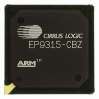
EP9315-CBZ Cirrus Logic Inc, EP9315-CBZ Datasheet - Page 17

EP9315-CBZ
Manufacturer Part Number
EP9315-CBZ
Description
IC ARM9 SOC ENH UNIV 352PBGA
Manufacturer
Cirrus Logic Inc
Series
EP9r
Specifications of EP9315-CBZ
Core Size
16/32-Bit
Core Processor
ARM9
Speed
200MHz
Connectivity
EBI/EMI, EIDE, Ethernet, I²C, IrDA, Keypad/Touchscreen, PCMCIA, SPI, UART/USART, USB
Peripherals
AC'97, DMA, I²:S, LCD, LED, MaverickKey, POR, PWM, WDT
Number Of I /o
16
Program Memory Type
ROMless
Ram Size
32K x 8
Voltage - Supply (vcc/vdd)
1.65 V ~ 3.6 V
Data Converters
A/D 8x12b
Oscillator Type
External
Operating Temperature
0°C ~ 70°C
Package / Case
352-BGA
Controller Family/series
(ARM9)
No. Of I/o's
16
Cpu Speed
200MHz
No. Of Timers
5
Digital Ic Case Style
BGA
Supply Voltage Range
1.65V To 1.94V, 3V To 3.6V
Embedded Interface Type
SPI
Rohs Compliant
Yes
Processor Series
EP93xx
Core
ARM920T
Data Bus Width
32 bit
3rd Party Development Tools
MDK-ARM, RL-ARM, ULINK2
Development Tools By Supplier
EDB9315A-Z
Case
BGA
Dc
06+
Lead Free Status / RoHS Status
Lead free / RoHS Compliant
For Use With
598-1144 - KIT DEVELOPMENT EP9315 ARM9
Eeprom Size
-
Program Memory Size
-
Lead Free Status / Rohs Status
Details
Other names
598-1139
Available stocks
Company
Part Number
Manufacturer
Quantity
Price
Part Number:
EP9315-CBZ
Manufacturer:
CIRRUS
Quantity:
20 000
- Current page: 17 of 824
- Download datasheet (13Mb)
Tables
DS785UM1
(Ports C, D, E, G, H) ....................................................................................................................................28-4
(Ports A, B, F) ..............................................................................................................................................28-5
Figure 25-1. Different Types of Touch Screens ..........................................................................................25-2
Figure 25-2. 8-Wire Resistive Interface Switching Diagram .......................................................................25-5
Figure 25-3. 4-Wire Analog Resistive Interface Switching Diagram............................................................25-6
Figure 25-4. Analog Resistive Touch Screen Scan Flow Chart ..................................................................25-9
Figure 25-5. 5-Wire Analog Resistive Interface Switching Diagram..........................................................25-11
Figure 25-6. 5-Wire Feedback (7-Wire) Analog Resistive Interface Switching Diagram ...........................25-12
Figure 25-7. Power Down Detect Press Switching Diagram .....................................................................25-13
Figure 25-8. Other Switching Diagrams ....................................................................................................25-14
Figure 25-9. Measure Resistance Switching Diagram ..............................................................................25-15
Figure 26-1. Key Array Block Diagram
Figure 26-2. 8 x 8 Key Array Diagram ......................................................................................................26-3
Figure 26-3. Apparent Key 00H...................................................................................................................26-4
Figure 27-1. IDE Interface Signal Connections ...........................................................................................27-2
Figure 28-1. System Level GPIO Connectivity ............................................................................................28-2
Figure 28-2. Signal Connections Within the Standard GPIO Port Control Logic
Figure 28-3. Signal Connections Within the Enhanced GPIO Port Control Logic
Table P-1. Frequency, Package, Applicable EP93xx Processor.................................................................. P-1
Table P-2. Chapter Number and Function, Applicable EP93xx Processor .................................................. P-1
Table 1-1. EP93xx Maximum Clock Rates, Package Type and Number of Balls .........................................1-1
Table 1-2. EP93xx Features Summary .........................................................................................................1-2
Table 2-1. AHB Arbiter Priority Scheme......................................................................................................2-10
Table 2-2. AHB Peripheral Address Range.................................................................................................2-11
Table 2-3. APB Peripheral Address Range.................................................................................................2-12
Table 2-4. ARM920T Core Operating Modes..............................................................................................2-13
Table 2-5. Register Organization Summary ................................................................................................2-14
Table 2-6. CP15 ARM920T Register Description........................................................................................2-15
Table 2-7. Global Memory Map for the Two Boot Modes............................................................................2-16
Table 2-8. Internal Register Map ................................................................................................................2-17
Table 3-1. Saturation for Non-accumulator Instructions................................................................................3-5
Table 3-2. Accumulator Bit Formats for Saturation .......................................................................................3-5
Table 3-3. Comparison Relationships and Their Results ..............................................................................3-7
Table 3-4. ARM® Condition Codes and Crunch Compare Results...............................................................3-7
Table 3-5. Condition Code Definitions.........................................................................................................3-15
...................................................................................................26-1
©
Copyright 2007 Cirrus Logic, Inc.
EP93xx User’s Guide
xvii
Related parts for EP9315-CBZ
Image
Part Number
Description
Manufacturer
Datasheet
Request
R

Part Number:
Description:
IC ARM920T MCU 200MHZ 352-PBGA
Manufacturer:
Cirrus Logic Inc
Datasheet:

Part Number:
Description:
32-Bit Microcontroller IC
Manufacturer:
Cirrus Logic Inc
Datasheet:

Part Number:
Description:
IC ARM920T MCU 200MHZ 352-PBGA
Manufacturer:
Cirrus Logic Inc
Datasheet:

Part Number:
Description:
MCU, MPU & DSP Development Tools Eval Bd Uni. ARM9 SOC Processor
Manufacturer:
Cirrus Logic Inc
Datasheet:

Part Number:
Description:
Development Kit
Manufacturer:
Cirrus Logic Inc
Datasheet:

Part Number:
Description:
Development Kit
Manufacturer:
Cirrus Logic Inc
Datasheet:

Part Number:
Description:
High-efficiency PFC + Fluorescent Lamp Driver Reference Design
Manufacturer:
Cirrus Logic Inc
Datasheet:

Part Number:
Description:
Development Kit
Manufacturer:
Cirrus Logic Inc
Datasheet:

Part Number:
Description:
Development Kit
Manufacturer:
Cirrus Logic Inc
Datasheet:

Part Number:
Description:
Development Kit
Manufacturer:
Cirrus Logic Inc
Datasheet:

Part Number:
Description:
Development Kit
Manufacturer:
Cirrus Logic Inc
Datasheet:

Part Number:
Description:
Development Kit
Manufacturer:
Cirrus Logic Inc
Datasheet:

Part Number:
Description:
Development Kit
Manufacturer:
Cirrus Logic Inc
Datasheet:

Part Number:
Description:
Ref Bd For Speakerbar MSA & DSP Products
Manufacturer:
Cirrus Logic Inc


