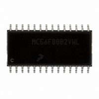
MC56F8002VWL Freescale Semiconductor, MC56F8002VWL Datasheet - Page 30

MC56F8002VWL
Manufacturer Part Number
MC56F8002VWL
Description
DSC 12K FLASH 32MHZ 28-SOIC
Manufacturer
Freescale Semiconductor
Series
56F8xxxr
Datasheet
1.MC56F8006DEMO.pdf
(100 pages)
Specifications of MC56F8002VWL
Core Processor
56800
Core Size
16-Bit
Speed
32MHz
Connectivity
I²C, LIN, SCI, SPI
Peripherals
LVD, POR, PWM, WDT
Number Of I /o
23
Program Memory Size
12KB (6K x 16)
Program Memory Type
FLASH
Ram Size
1K x 16
Voltage - Supply (vcc/vdd)
1.8 V ~ 3.6 V
Data Converters
A/D 15x12b
Oscillator Type
Internal
Operating Temperature
-40°C ~ 105°C
Package / Case
28-SOIC
Product
DSCs
Data Bus Width
16 bit
Processor Series
MC56F80xx
Core
56800E
Instruction Set Architecture
Dual Harvard
Device Million Instructions Per Second
32 MIPs
Maximum Clock Frequency
32 MHz
Number Of Programmable I/os
40
Data Ram Size
2 KB
Operating Supply Voltage
1.8 V to 3.6 V
Maximum Operating Temperature
+ 105 C
Mounting Style
SMD/SMT
Development Tools By Supplier
MC56F8006DEMO, APMOTOR56F8000E
Interface Type
LIN, I2C, SCI, SPI
Minimum Operating Temperature
- 40 C
For Use With
APMOTOR56F8000E - KIT DEMO MOTOR CTRL SYSTEM
Lead Free Status / RoHS Status
Lead free / RoHS Compliant
Eeprom Size
-
Lead Free Status / Rohs Status
Lead free / RoHS Compliant
Available stocks
Company
Part Number
Manufacturer
Quantity
Price
Part Number:
MC56F8002VWL
Manufacturer:
FREESCALE
Quantity:
20 000
Memory Maps
On-chip RAM is also mapped into program space starting at P: 0x00 8000. This makes for easier online reprogramming of
on-chip flash.
5.4
The location of the vector table is determined by the vector base address register (VBA). The value in this register is used as
the upper 14 bits of the interrupt vector VAB[20:0]. The lower seven bits are determined based on the highest priority interrupt
and are then appended onto VBA before presenting the full VAB to the core. Please see the MC56F8006 Peripheral Reference
Manual for detail. The reset startup addresses of 56F8002 and 56F8006 are different.
By default, the chip reset address and COP reset address correspond to vector 0 and 1 of the interrupt vector table. In these
instances, the first two locations in the vector table must contain branch or JMP instructions. All other entries must contain JSR
instructions.
The highest number vector, a user assignable vector USER6 (vector 50), can be defined as a fast interrupt if the instruction
located in this vector location is not a JSR or BSR instruction. Please see section 9.3.3.3 of DSP56800E 16-Bit Core Reference
Manual for detail.
30
•
•
56F8006 startup address is located at 0x00 0000. The reset value of VBA is reset to a value of 0x0000 that corresponds
to address 0x00 0000
56F8002 startup address is located at 0x00 0800. The reset value of VBA is reset to a value of 0x0010 that corresponds
to address 0x00 0800
0x00 0000
0x00 2000
0x00 0000
0x00 8400
0x00 0800
0x00 8400
0x00 2000
0x00 8000
0x00 8000
Interrupt Vector Table and Reset Vector
Reserved
Reserved
Reserved
Reserved
Reserved
Program
Program
RAM
Flash
RAM
Flash
MC56F8006/MC56F8002 Digital Signal Controller, Rev. 3
Figure 7. 56F8006 Dual Port RAM Map
Figure 8. 56F8002 Dual Port RAM Map
Dual Port RAM
Dual Port RAM
Peripherals
Peripherals
Reserved
Reserved
Reserved
Reserved
EOnCE
EOnCE
Data
Data
RAM
RAM
Freescale Semiconductor
0xFF FF00
0x00 0000
0xFF FF00
0x00 F000
0x00 0000
0x01 0000
0x00 F000
0x00 0400
0x01 0000
0x00 0400


