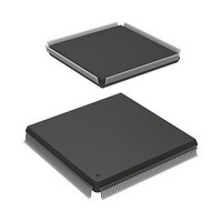
HD6417727F100V Renesas Electronics America, HD6417727F100V Datasheet - Page 39

HD6417727F100V
Manufacturer Part Number
HD6417727F100V
Description
MPU 3V 16K PB-FREE 240-QFP
Manufacturer
Renesas Electronics America
Series
SuperH® SH7700r
Datasheet
1.HD6417727BP100CV.pdf
(1098 pages)
Specifications of HD6417727F100V
Core Processor
SH-3 DSP
Core Size
32-Bit
Speed
100MHz
Connectivity
FIFO, SCI, SIO, SmartCard, USB
Peripherals
DMA, LCD, POR, WDT
Number Of I /o
104
Program Memory Type
ROMless
Ram Size
32K x 8
Voltage - Supply (vcc/vdd)
1.6 V ~ 2.05 V
Data Converters
A/D 6x10b; D/A 2x8b
Oscillator Type
Internal
Operating Temperature
-20°C ~ 75°C
Package / Case
240-QFP
Lead Free Status / RoHS Status
Lead free / RoHS Compliant
Eeprom Size
-
Program Memory Size
-
Available stocks
Company
Part Number
Manufacturer
Quantity
Price
Company:
Part Number:
HD6417727F100V
Manufacturer:
Renesas Electronics America
Quantity:
10 000
- Current page: 39 of 1098
- Download datasheet (7Mb)
Section 1 Overview and Pin Functions
Figure 1.1
Figure 1.2
Figure 1.3
Section 2 CPU
Figure 2.1
Figure 2.2
Figure 2.3
Figure 2.4
Figure 2.5
Figure 2.5
Figure 2.6
Figure 2.7
Figure 2.8
Figure 2.9
Figure 2.10 Data Format............................................................................................................ 39
Figure 2.11 Byte, Word, and Longword Alignment .................................................................. 40
Figure 2.12 X and Y Data Transfer Addressing ........................................................................ 49
Figure 2.13 Single Data Transfer Addressing............................................................................ 50
Figure 2.14 Modulo Addressing ................................................................................................ 52
Figure 2.15 DSP Instruction Formats ........................................................................................ 58
Figure 2.16 Sample Parallel Instruction Program...................................................................... 87
Figure 2.17 Examples of Conditional Operations and Data Transfer Instructions .................... 95
Section 3 Memory Management Unit (MMU)
Figure 3.1
Figure 3.2
Figure 3.3
Figure 3.4
Figure 3.5
Figure 3.6
Figure 3.7
Figure 3.8
Figure 3.9
Figure 3.10 Synonym Problem .................................................................................................. 115
Figure 3.11 MMU Exception Generation Flowchart ................................................................. 120
Figure 3.12 MMU Exception Signals in Instruction Fetch ........................................................ 121
Figure 3.13 MMU Exception Signals in Data Access ............................................................... 122
Block Diagram .......................................................................................................
Pin Arrangement (PRQP0240KC-B) .....................................................................
Pin Arrangement (PLBG0240JA-A) ...................................................................... 10
Register Configuration in Each Processing Mode (1) ............................................ 23
Register Configuration in Each Processing Mode (2) ............................................ 24
General Purpose Register (Not in DSP Mode) ....................................................... 25
General Purpose Register (DSP Mode) .................................................................. 26
Control Registers (1) .............................................................................................. 29
Control Registers (2) .............................................................................................. 30
System Registers .................................................................................................... 31
DSP Registers......................................................................................................... 35
Connections of DSP Registers and Buses .............................................................. 37
Longword Operand ................................................................................................ 38
MMU Functions ..................................................................................................... 99
Logical Address Space Mapping............................................................................ 101
MMU Register Contents ........................................................................................ 104
Overall Configuration of the TLB.......................................................................... 105
Logical Address and TLB Structure....................................................................... 106
TLB Indexing (IX = 1) ........................................................................................... 107
TLB Indexing (IX = 0) ........................................................................................... 108
Objects of Address Comparison............................................................................. 109
Operation of LDTLB Instruction............................................................................ 113
Figures
Rev.6.00 Mar. 27, 2009 Page xxxvii of lvi
REJ09B0254-0600
8
9
Related parts for HD6417727F100V
Image
Part Number
Description
Manufacturer
Datasheet
Request
R

Part Number:
Description:
KIT STARTER FOR M16C/29
Manufacturer:
Renesas Electronics America
Datasheet:

Part Number:
Description:
KIT STARTER FOR R8C/2D
Manufacturer:
Renesas Electronics America
Datasheet:

Part Number:
Description:
R0K33062P STARTER KIT
Manufacturer:
Renesas Electronics America
Datasheet:

Part Number:
Description:
KIT STARTER FOR R8C/23 E8A
Manufacturer:
Renesas Electronics America
Datasheet:

Part Number:
Description:
KIT STARTER FOR R8C/25
Manufacturer:
Renesas Electronics America
Datasheet:

Part Number:
Description:
KIT STARTER H8S2456 SHARPE DSPLY
Manufacturer:
Renesas Electronics America
Datasheet:

Part Number:
Description:
KIT STARTER FOR R8C38C
Manufacturer:
Renesas Electronics America
Datasheet:

Part Number:
Description:
KIT STARTER FOR R8C35C
Manufacturer:
Renesas Electronics America
Datasheet:

Part Number:
Description:
KIT STARTER FOR R8CL3AC+LCD APPS
Manufacturer:
Renesas Electronics America
Datasheet:

Part Number:
Description:
KIT STARTER FOR RX610
Manufacturer:
Renesas Electronics America
Datasheet:

Part Number:
Description:
KIT STARTER FOR R32C/118
Manufacturer:
Renesas Electronics America
Datasheet:

Part Number:
Description:
KIT DEV RSK-R8C/26-29
Manufacturer:
Renesas Electronics America
Datasheet:

Part Number:
Description:
KIT STARTER FOR SH7124
Manufacturer:
Renesas Electronics America
Datasheet:

Part Number:
Description:
KIT STARTER FOR H8SX/1622
Manufacturer:
Renesas Electronics America
Datasheet:

Part Number:
Description:
KIT DEV FOR SH7203
Manufacturer:
Renesas Electronics America
Datasheet:


