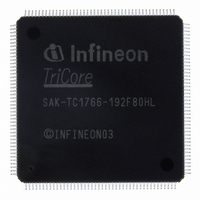
SAK-TC1766-192F80HL BD Infineon Technologies, SAK-TC1766-192F80HL BD Datasheet - Page 68

SAK-TC1766-192F80HL BD
Manufacturer Part Number
SAK-TC1766-192F80HL BD
Description
IC MCU 32BIT FLASH PG-LQFP-176
Manufacturer
Infineon Technologies
Series
TC17xxr
Datasheet
1.SAK-TC1766-192F80HL_BD.pdf
(117 pages)
Specifications of SAK-TC1766-192F80HL BD
Core Processor
TriCore
Core Size
32-Bit
Speed
80MHz
Connectivity
ASC, CAN, MLI, MSC, SSC
Peripherals
DMA, POR, WDT
Number Of I /o
81
Program Memory Size
1.5MB (1.5M x 8)
Program Memory Type
FLASH
Ram Size
108K x 8
Voltage - Supply (vcc/vdd)
1.42 V ~ 1.58 V
Data Converters
A/D 2x10b; A/D 32x8b,10b,12b
Oscillator Type
External
Operating Temperature
-40°C ~ 125°C
Package / Case
176-LFQFP
Packages
PG-LQFP-176
Max Clock Frequency
80.0 MHz
Sram (incl. Cache)
108.0 KByte
Can Nodes
2
A / D Input Lines (incl. Fadc)
36
Program Memory
1.5 MB
For Use With
B158-H8539-G2-X-7600IN - KIT STARTER TC176X SERIES
Lead Free Status / RoHS Status
Lead free / RoHS Compliant
Eeprom Size
-
Other names
KT1766192F80HLBDXT
SAK-TC1766-192F80HLBDINTR
SAK-TC1766-192F80HLBDINTR
Preliminary
Figure 3-15 Clock Generation Unit
Recommended Oscillator Circuits
The oscillator circuit, a Pierce oscillator, is designed to work with both, an external crystal
oscillator or an external stable clock source. It basically consists of an inverting amplifier
and a feedback element with XTAL1 as input, and XTAL2 as output.
When using a crystal, a proper external oscillator circuitry must be connected to both
pins, XTAL1 and XTAL2. The crystal frequency can be within the range of 4 MHz
to 25 MHz. Additionally, it is necessary to have two load capacitances
depending on the crystal type, a series resistor
may be temporarily inserted to measure the oscillation allowance (negative resistance)
of the oscillator circuitry.
and
resistance evaluation and for non-productive systems. The exact values and related
operating range are dependent on the crystal frequency and have to be determined and
optimized together with the crystal vendor using the negative resistance method.
Data Sheet
XTAL1
XTAL2
BYPASS
OSC_
BYPASS
are derived from
equal to
C
X2
values shown in
OGC
Oscillator
f
Circuit
CPU
OSC_CON
MOSC
Register
.
Osc. Run
Detect.
f
OSCR
OSC
f
VCO
R
only by the K-Divider. In this mode, the system clock
Q
Figure 3-16
PDIV
[2:0]
Divi-
values are typically specified by the crystal vendor. The
der
P
OSC
DISC
Clock Generation Unit (CGU)
1
Detector
System Control Unit (SCU)
Lock
PLL_
LOCK
can be used as starting points for the negative
PLL
64
Detect.
Phase
Register PLL_CLC
R
Divider
NDIV
[6:0]
X2
N
VCO
, to limit the current. A test resistor
VCO_
SEL[1:0]
f
VCO
VCO_
BYPASS
1
0
M
U
X
Functional Description
KDIV
[3:0]
Divider
Divider
K:1
1:1
C
SYS
FSL
X1
and
V1.0, 2008-04
PLL_
BYPASS
M
U
X
MCA06083
TC1766
C
X2
f
f
f
SYS
SYS
CPU
, and
C
R
X1
is
Q


